7
2. MOUNTING THE FLOW METER (Liquid Applications)
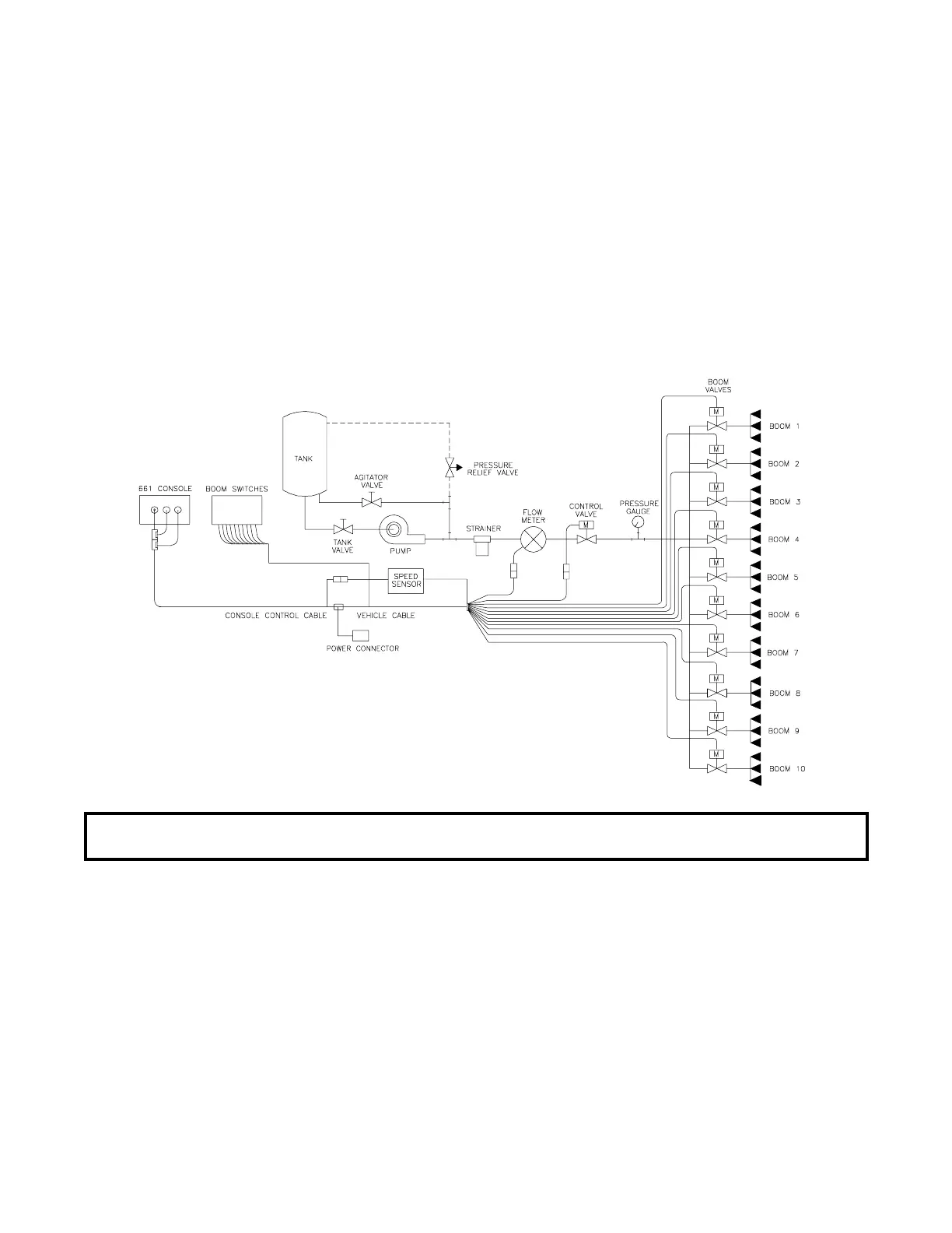
1) Mount Flow Meter in the area of the boom valves per Figure 4. All flow through Flow Meter must go
to booms only, i.e., no return line to tank or pump after Flow Meter.
2) Mount Flow Meter horizontal to the ground. Use the bracket to secure the Flow Meter.
3) For best results, allow a minimum of 7 1/2 inches [20 cm] of straight hose on inlet of Flow Meter.
Bend radius of hose on outlet of Flow Meter should be gradual.
4) Flow must be in direction of arrow on Flow Meter.
3. MOUNTING THE CONTROL VALVE (Liquid Applications)
1) Mount the motorized Control Valve in the main hose line between the Flow Meter and the booms,
with motor in the upright position.
2) Connect the Vehicle Cable connectors to boom valves, Flow Meter, and motorized Control Valve.
(Black wire to boom valve #1, Brown to boom valve #2, Blue to boom valve #3, Blk/wht to boom valve
#4, Brn/wht to boom valve #5, Blu/wht to boom valve #6, Wht/blk to boom valve #7, wht/brn to boom
valve #8, wht/blue to boom valve #9, pink to boom valve #10).
NOTE: It is critical, when using suspensions, that the system be thoroughly rinsed out
each day after use.
FIGURE 4
 Loading...