P/N 016-9001-022 Rev. D 23
VIPER 4
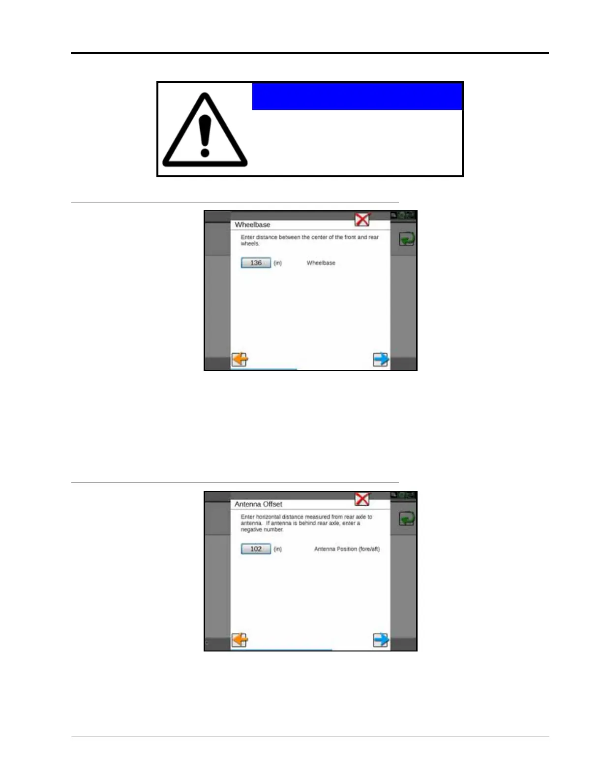
FIGURE 19. Wheel Base Configuration Screen
1. To figure the machine’s wheel base, measure the distance from the center of the machine’s front axle to the
center of the rear axle.
2. Select the value box to enter the Wheel Base measurement using the on-screen keypad.
3. Select Next.
4. To figure the GPS Antenna Position, measure the distance from the antenna to the center of the rear axle.
FIGURE 20. Antenna Position Configuration Screen
5. Select the value box to enter the Antenna Position measurement using the on-screen keypad.
IMPORTANT: If the antenna is in front of the rear axle, the number entered must be positive. If the antenna is behind the
rear axle, the number must be entered as negative using a “ - “ before the number. For example, if the
NOTICE
The Wheel Base, Antenna Position, and Antenna
Height values are critical to the operation of the
SmarTrax system. Measure these dimensions
accurately to ensure optimal SmarTrax system
performance!
 Loading...


