Note:IfyouarettingtheAISunittoberglassthathasagelcoat
surface,overdrillthesurfacetopreventthegelcoatfromdamage
whensecuringthescrews.Beforedrillingthepilotholes,hand
drillthemarkedlocationswithanoversizedbitandcountersink
toapproximately9.5mm(3/8in)diameter.
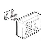
1.Ensurethattheintendedinstallationsitemeetstheconditions
describedunderSiterequirements.
2.Usingapencil,offeruptheunitandmarkthelocationofthe
screwholesonthemountingsurface.
3.Drillthemountingholesusinga3.2mm(1/8”)drillbit.
4.Parttthescrews.
5.Placetheunitoverthescrewsandmoveunitdowntolockin
position
6.Fullytightenthescrews.
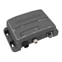
3.5Systemchecks
Switchingon
WhenpoweredontheLEDStatusindicatorshallbebrightgreen
andwilltoggletodimwhenmessagesarereceived.
Whentheinstallationiscomplete,observetheSTATUSindicator
and:
1.SwitchonpowertotheAISreceiver.
2.Checkthat:
i.WhenpoweredontheLEDStatusindicatorshallbebright
GREENandwilltoggletodimGREENwhenmessagesare
received.
Checkingforinterference
Postinstallationcheck
Ifyouhaveinstalledanysystemaboardaboatormadeother
changestotheboat’selectronicsystems(radar,VHFradioetc.),
youneedtocheckbeforecastingoff,thatallelectricalsystems
operatesatisfactorilywithoutanyundueelectricalinterference,
inordertoconformwithElectroMagneticCompatibility(EMC)
regulations.Todothis:
1.Ensuringitissafetodoso,turnonallelectronicsystemsaboard
yourvessel.
2.Checkthattheelectronicsystemsalloperatesatisfactorily.
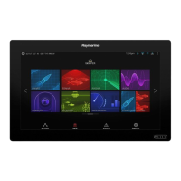
UsingAIS
TheexactmethodofusingAISdependsonwhichtypeofRaymarine
multifunctiondisplayyouareusing.
Refertothehandbookforyourmultifunctiondisplayforinformation
onusingyourAIS.
AIS350Receiver39
 Loading...