16 DSM300 Installation Manual
The RED wire must be connected to the feed from the positive (+) battery terminal
and the BLACK wire to the feed from the negative (–) battery terminal. The shield
wire (drain) should be connected to the boat’s RF ground. See “Ground
Connection” on page 17.
Install a quick blow 8 amp fuse on the red (positive) wire.
CAUTION:
If the power connections are accidentally reversed the system
will not work. Use a multimeter to ensure that the input power
leads are connected for correct polarity.
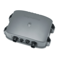
There is no power switch on the DSM300. The unit turns on when the power cord
is attached to boat’s power and plugged into the POWER connector on the
connector panel.
Note:
You should locate the DSM300 so that the power cord can be easily removed, if
necessary. If the sounder is placed in a difficult-to-reach location, Raymarine strongly
suggests installing an on/off switch on the DSM300 power cord at a point where it is easily
accessible.
Figure 1-6: Power Connector
Pin No. Function Color
1 Battery positive (12/24/32 V systems) Red
2 Battery negative Black
3 Shield (drain wire) No insulation
1
2
3
D6162-1

 Loading...