Chapter 1: DSM300 Installation 15
1.6 System Connections
The connector panel provides the following connection sockets:
•
T/D, 7-pin socket for connecting to the transducer
•
HSB2, 4-pin socket for connecting to a C Series or hsb
2
PLUS Series display
•
POWER, 3-pin socket for connecting to boat’s DC power systems rated from
10.7 V to 32 V and one RF ground (screen) connection
•
SEATALK HS, RJ-45 socket for connecting to an E Series display
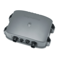
Figure 1-4: DSM300 Connector Panel
CAUTION:
To protect exposed pins, please place the attached dust cover
over the socket (4-pin or RJ-45) to which you are not connecting a
cable.
The following sections detail the connectors used when installing the DSM300.
DC Power Connection
The DSM300 is intended for use on boat’s DC power systems rated from 10.7 V to
32 V.
The power connection to the unit should be made at either the output of the
battery isolator switch or at a DC power distribution panel. Power should be fed
directly to the DSM300 via its own dedicated cable system and protected by a
thermal circuit breaker or fuse on the red (positive) wire that is installed close to
the power connection.
DC power is connected at the 3-pin POWER connector on the unit’s connector
panel. The connector (viewed from the outside) and pin functions are shown in
the following diagram and table.
D7464-1
10.7 to 32 VDC
E Series Display
Transducer
C Series or hsb PLUS
2

 Loading...