4.4Dataandcontrolconnections
Theillustrationsbelowareexamplesofhowtheunitcanbe
connectedtoSeaT alk
ng
andacompatibleengine’sCANbusto
enableenginedatatransmissionandsteeringcontrol.
Important:RaymarinedoesnotrecommendthattheECI-100
isusedonthesameCANbusasother3
rd
partygateway
products.TheECI-100shouldbeusedtoreplaceexisting
gatewayproductsinyoursystem.
Note:Theillustrationsbelowareexamplesonly.EngineCAN
busconnectionsaremadeusingeithera‘Y’loomcable,CAN
bushuboratrailinglead.Theconnectionmethodwilldiffer
dependingonenginemanufacturer.TheSeaT alk
ng
connection
remainsthesameregardlessofenginemanufacturer.
Fordetailsoncompatibleenginesandsteeringsystemsplease
refertotheSupportedengines/steeringsystemssection.
SingleengineCANbus‘Y’loomconnection
Dependingonenginemanufacturertheunitmaybeconnected
usinga‘Y’loomcableasshownbelow.Thisconnectionmethod
shouldnormallybeusedwhenaCANbushubisnotpresent.
ItemDescription
1
SeaTalk
ng
spurcableconnectionbetweentheSeaTalk
ng
backboneandtheEV2’sSeaTalk
ng
connector.
2
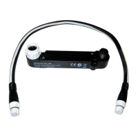
ECI-100unit
3
SeaTalk
ng
networkpowersupply(12Vdc)
4YLoomcable
5
EV2—Evolution
TM
autopilot
6
Engine-specicadaptorcable
7
EngineCANbus
SingleengineCANbusmulti-linkhubconnection
WhereavailabletheunitshouldbeconnectedusingtheCAN
bushub.
ItemDescription
1
SeaTalk
ng
spurcableconnectionbetweentheSeaTalk
ng
backboneandtheEV2’sSeaTalk
ng
connector.
2
ECI-100unit
3
SeaTalk
ng
networkpowersupply(12Vdc)
ItemDescription
4EV2—Evolution
TM
autopilot
5
Engine-specicadaptorcable
6
EngineCANbus
7
CANbushub
MultiCANbusconnection
OnvesselswhichhaveadedicatedCANbusforeachengine,1
unitisrequiredperCANbus.
ItemDescription
1
Engine1CANbus
2Trailinglead
3
Engine-specicadaptorcable.
4
ECI–100
5
SeaTalk
ng
networkpowersupply(12Vdc)
6
Engine2CANbus
Fordetailsonavailablenetworkhardwareandcablesreferto
Chapter10Sparesandaccessories.
Ifyourenginedataappearsinthewrongorderontheengine
datapagesofyourmultifunctiondisplayyoucancorrectthisby
runningtheengineidenticationwizard.
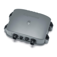
ECI–100
 Loading...
