ACU (control unit) connection
A B+
_
MOTOR
POWER
D134951
Terminal
identification
stripes
Drive wire
(brown).
Insert into
2-stripe
terminal
To the
ACU
Rear of
socket
Drive wire
(blue).
Insert into
3-stripe
terminal
Tiller ACU
Blue Brown
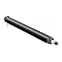
• Connect the tiller drive to the control unit via the waterproof plug
and socket (supplied).
• The plug comes ready assembled to the tiller drive.
• Mount the socket in the cockpit next to the tiller drive.
Cabling
1. Measure the total length of cable run from the control unit to the
socket location.
Use this table to identify the appropriate power cable size:
2. Route the cable from the control unit to the socket location.
Cable length Copper area AWG
Up to 2.5 m (8 ft) 1.0 mm
2
18
Up to 4.0 m (13 ft) 1.5 mm
2
16
Up to 6.0 m (22 ft) 2.5 mm
2
14
NOTE: You can use the autopilot control head to change the Motor phase:
MENU > Setup > Autopilot Calibration > Drive Settings > Motor Phasing
3. Connect the wires as shown to the tiller socket.
4. Connect the wires as shown to the Motor terminals on the ACU control unit.
 Loading...