Do you have a question about the Raymarine LIGHTHOUSE 3 and is the answer not in the manual?
Product is an aid to navigation; captain's judgment and official charts are paramount for safe navigation.
Do not rely solely on auto-generated routes; review and edit them carefully for safety.
Ensure personnel are clear of the scanner when the radar is transmitting electromagnetic energy.
Never operate sonar with transducer out of water, touch transducer face, or if divers are nearby.
Details new features added to LightHouse 3 v3.14.88, including First Responder and Wi-Fi improvements.
Initial setup steps for a new MFD, including power on, data master selection, and startup wizard.
Lists the actions required for the first power up of a new Multifunction Display (MFD).
Explains the Data master designation in networks with multiple MFDs and its default setting.
Steps to configure transducer settings in the Fishfinder app, including depth and temperature.
Guide to calibrating RealVision™ 3D transducers which include a built-in AHRS sensor.
Instructions for calibrating transducers connected via the iTC-5 Instrument Transducer Converter.
Instructions for performing a settings reset or a factory reset, noting data loss implications.
Warning to ensure card reader cover or door is closed to prevent water ingress.
Information on obtaining and installing software updates for Raymarine products.
Steps to update software using a MicroSD card, including checking versions and downloading.
Steps to update software via the internet, including Wi-Fi connection setup.
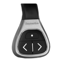
Instructions for pairing RMK remote keypads, Quantum Radar scanners, and Bluetooth speakers.
Steps to pair an RMK keypad with the MFD for remote control.
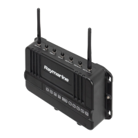
Prerequisites and steps for connecting a Quantum Radar scanner to the MFD using Wi-Fi.
Steps to pair a Bluetooth speaker with the MFD, ensuring it is discoverable.
Explanation of alarms, their severity coding (Red, Orange, Blue), and the Alarm manager.
Functionality to list, enable/disable alarms, adjust thresholds, and view alarm history.
How to access the Alarm manager to view active alarms from the Homescreen.
Enabling/disabling and setting thresholds for various alarms like Radar, AIS, and Waypoint arrival.
Alarm triggered when Radar targets pose a potential collision risk within specified distance and time.
Alarm triggered when dangerous Radar targets are lost, indicating no return for 20 seconds.
Alarm triggered when AIS targets pose a potential collision risk within specified distance and time.
Alarm triggered when Radar returns are detected within Guard Zone 1.
Alarm triggered when Radar returns are detected within Guard Zone 2.
Alarm triggered upon arrival at a waypoint, with configurable radius sizes for arrival alarms.
Alarm triggered during navigation when vessel steers off track by more than specified Cross track error.
Alarm triggered when vessel drifts from anchor position by more than specified Drift range.
Alarm triggered when fuel remaining in tanks reaches specified Fuel level.
Alarm triggered when a charted obstruction conflicts with Safety depth or height settings.
Steps to acknowledge an active alarm, dismiss notification and stop audible tone.
Using the Man Overboard (MOB) feature to mark the vessel's position when an object falls overboard.
Displaying DSC distress alerts received by a connected DSC VHF radio on the MFD.
Enabling/disabling Autopilot control, setting response, and accessing advanced autopilot settings.
Settings for First responder features, STEDS specific features, and AIS5000 connection.
Ensuring correct operation by setting boat details like icon, name, type, and safety margins.
Importance of calibrating tank levels for accuracy and editing/calibrating on Boat details page.
Designating a Data master MFD in systems with multiple MFDs for data sharing.
Connecting MFDs to a wireless display using an external dongle or built-in support.
Pre-commissioning checks, steps, vessel hull type selection, and dockside calibration procedures.
Checks for correct installation, software updates, and familiarity with system components.
Required steps for commissioning the autopilot system, performed in the correct order.
Selecting the vessel hull type that best matches steering characteristics for optimum performance.
The dockside calibration process, guided by a wizard, includes drive type, rudder limit, and drive checks.
Procedure for aligning the rudder, applicable to systems with a rudder reference transducer.
Setting the rudder limit to prevent impact with end stops and unnecessary load on the steering system.
Specifying the time for the rudder to move from hard port to hard starboard, or vice versa.
Ensures adequate provision to prevent steering mechanism impact on end stops if no rudder reference is fitted.
System checks drive connection and asks if safe to take helm, then moves rudder.
System checks drive connection and asks for confirmation of rudder movement.
Instructions for setting the hard-over time for vessels without a rudder reference transducer.
Process of EV sensor's internal compass compensating for magnetic fields through automatic linearization.
Linearization required after EV sensor installation or factory reset; progress shown in Autopilot settings.
Using the MFD as an Evolution autopilot controller and enabling/disabling control.
Steps to engage autopilot in locked heading mode for Wheel and Tiller pilots.
Steps to engage autopilot in Navigation (Track) mode, including Goto or Follow.
Process for engaging autopilot using physical buttons on RMK keypad or Axiom Pro.
How to disengage the autopilot at any time by selecting the Disengage pilot icon.
Menu items for Autopilot setup: Vessel hull type, Drive type, Compass offset, Speed input, Cruise speed, Calibration lock, Dockside wizard, Restart compass, Compass lock, Align compass to GPS, Pilot factory reset, CCU debug level, ACU debug level, Rudder damping, Auto turn angle, Power steering, Reverse rudder ref.
Explanation of rudder damping levels and deadband angles to prevent autopilot hunting.
Procedure to adjust Rudder Damping level via Homescreen > Settings > Autopilot > Advanced settings > Rudder Damping.
Do not rely solely on auto-routes; review, edit, and ensure safety of route legs.
Auto-route generation does not adhere to traffic separation schemes; switch off for routes near traffic lanes.
Auto-route generation uses minimum safe settings to restrict routes from unsuitable areas.
Ensuring safety by checking route legs, waypoints, and obstructions before following.
Displays vessel relative to land and charted objects for planning and navigation using GNSS position.
About the Chart app's base map and required ENC or RNC charts for navigation purposes.
Precautions to avoid irreparable damage or data loss from chart and memory cards.
Using S-63 Encrypted Charts (ENC) data with MFD activation file for secure, compressed charts.
Process for installing S-63 Encrypted Charts, requiring specific steps and potentially multiple memory cards.
Steps to obtain an S-63 MFD activation file specific to your MFD for chart display and use.
Installation of base cell files and cell permits required for S-63 Encrypted Charts usage.
Installation of cumulative update files containing updated cartographic data for S-63 charts.
Performing a 'Goto' to a waypoint or location, and restarting cross track error (XTE).
Steps to perform a 'Goto' to a waypoint or specific location using the context menu.
Plotting a new course from current position to destination when route diverges from original plan.
Starting active navigation/follow a route from its starting waypoint using the Chart app.
Starting active navigation/follow a route from any waypoint using the Chart app.
Display of water depth measurements (soundings) and depth contours on charts.
Lines on cartography connecting equal depth points, creating underwater bottom structure visualization.
Tracking various target types (AIS, Radar, DSC, Intel, TOI) to improve situational awareness and collision avoidance.
Using AIS icons to identify AIS targets onscreen, with default and enhanced icon options.
Options for AIS targets: View full data, Add/Remove as buddy, Edit buddy name, Intercept.
Steps to manually acquire a Radar target using MARPA via context menu.
Options for Radar targets: Cancel target, Show CPA, Target info, Intercept.
Configuring Radar settings: Radar selection, Transmit, Dual range, Channel, Sync range with chart, Show Radar overlay, Visibility, Palette, Sector blanking, Doppler.
Displaying predicted future path of targets using vectors, history, and trail graphics.
Features for collision avoidance: Dangerous targets alarm, Radar guard zones, Predicted areas of danger, LightHouse chart obstruction alarm.
Notifies if Radar or AIS target will reach specified distance within specified time.
Tracks Radar/AIS targets relative to vessel's COG/SOG, showing interception lines and zones.
Enabling Predicted areas of danger for AIS and Radar targets in Chart app.
Using Intercept feature to rendezvous with friends or intercept vessels, plotting a direct course.
Understanding IRPCS/COLREGS, AIS feature, and Target interception implications is vital.
Displays tide animation, station symbols, and own vessel tide vector. Requires accurate date information.
Creating personal bathymetric charts in realtime using transducer depth readings and contour lines.
Steps to set up RealBathy: insert chart card, select cartography, enter waterline to transducer distance, enable RealBathy.
Measuring distances from vessel or between 2 points using the Chart context menu Measure feature.
Using SAR patterns (routes) to find objects in water, considering tide effects.
Creating a Sector Search pattern using Commence Search Point, Drift, Track spacing, Search Speed, and Leg time.
Creating an Expanding Square search pattern, an outwards spiralling square pattern for detailed searches.
Covers rectangular area, searched via Creeping (one end) or Parallel (lengthways) methods.
Steps to create Creeping/Parallel line patterns: Set CSP, Search Speed, Track Spacing, Define Search Rectangle.
Used in sailing to show how far to sail on current tack to reach waypoint, considering wind and tidal current.
Settings for laylines: Sail Performance profile (Fixed/Polar), Upwind/Downwind angles, Polar table, Display Laylines.
Features to assist in approaching race start line at optimum speed, angle, and time.
Creating a Race Start Line by placing port and starboard end points using chart waypoints or vessel's location.
Using vessel's location to ping each end of the Race Start Line, compensating for GPS location distance.
Starting the Race Timer for countdown until race start, with configurable duration (1-30 minutes).
Augmented Reality features in Chart app available with AR200 and compatible IP camera.
Displaying UAV icon on Chart app representing position when compatible UAV with GNSS is connected.
Creating personal bathymetric charts in realtime using depth transducer and SonarChart Live feature.
Steps to enable SonarChart Live: select Depth tab, enable Sonar logging, SonarChart Live, and Visibility.
Lists settings applicable to Chart app, dependent on cartography, and subscription requirements.
Enables/disables ClearCruise™ Augmented Reality camera's field of view (FOV) overlay.
Enables collision avoidance interception zone layer for AIS targets.
Enables collision avoidance interception zone layer for Radar targets.
Settings for Show soundings, Show contours, Shallow contour, Safe contour, Deep contour, Depth gradient, Deep water color, Record depth data, Waterline to tdcr, Save to, RealBathy, Visibility, Height correction, Density.
Determines depth at which Safe contour is displayed; must match Minimum safe depth.
Tab available when Sailing activity is selected; includes Sail Performance, Upwind/Downwind angles, Polar, Display Laylines, Adjust for tides, Boat type.
Displays echo visualization from Sonar module/transducer, compatible with various sonar types.
Warning indicates issues like sonar module powering up, connection problems, or no transducer.
Warning displayed when Sonar module cannot connect to transducer; check connections.
Available sonar channels depend on Sonar module and connected transducer: RealVision 3D, SideVision, DownVision, etc.
Placing a waypoint at an observed location in Fishfinder app to find the area again.
Viewing sonar history by scrolling back using swipe gestures or Pause icon.
Adjusting Sensitivity controls (Gain, Intensity, Surface Filter) for optimal image using onscreen icon or menu.
Lists settings for Fishfinder app: Sonar display tab, RealVision 3D tab, Transducer tab, Sounder tab.
Settings for Sounder name, Ping enable, Ping rate limit, Power mode, Ping rate, Dual channel ping mode, Tune frequency, AHRS stabilization, Reverse Port/Starboard, Interference rejection, 2nd echo rejection, Reset sounder, Reset trip.
Settings for Fish detection beep, Fish icons, Fish depth labels, Detection sensitivity, Ignore fish shallower/deeper than.
Visualizes echoes from Radar scanner for collision/situational awareness, tracking targets.
Comparison of features and settings available in Radar app based on connected Radar scanner type.
Features: Doppler, Dual Range, Interference Rejection, Target Expansion, Guard Zones, Radar Targets, Auto acquire, Tuning, Transmit Frequency.
Aligning Radar image correctly relative to vessel's bow for accurate bearing.
Selecting a Radar scanner for each Radar app instance and configuring Dual range.
Choosing which Radar scanner to use in Radar app instances, persists over power cycle.
Enables viewing 2 ranges (Short and Long) simultaneously on HD and SuperHD Radar scanners.
Configuring Radar to transmit periodically to conserve power, using Time Transmit and Standby settings.
Ensuring Radar objects appear at correct bearing relative to vessel's bow; check alignment for new installation.
Aligning bow with stationary object, reducing gain, and checking position relative to heading marker.
Adjusting Bearing alignment setting until target object appears under SHM.
Identifying target's range and bearing from vessel using Radar app.
Used to determine targets range and bearing from vessel or other target; two VRM/EBLs available.
Displaying AIS targets automatically in Chart and Radar apps when compatible AIS hardware is connected.
Configuring AIS target settings: Show AIS targets, Enhanced AIS targets, AIS names, Show AIS types, Hide static targets, Silent mode.
Tracking Radar targets in Chart and Radar apps, acquired manually or automatically via Guard zones.
Radar target symbols identifying Radar targets onscreen, displayed in Radar app and Chart app overlay.
Acquiring Radar targets automatically when they enter or appear in chosen Guard Zone(s).
Configuring automatic target acquisition: enabling switch, choosing Guard zone, enabling notifications.
Displaying target vectors, history, and object trail graphics for situational and collision awareness.
Notifies if Radar or AIS target will reach specified distance within specified time.
Alerts if Radar return is detected within configurable Guard zone areas.
Configuring Guard zone as sector or circle, adjusting size and sensitivity.
Doppler Radar technology for tracking moving targets with significant ground speed (>3 knots).
Enabling/disabling Doppler mode, changing color palette for Red (approaching) and Green (away) targets.
Manually setting blank sectors to hide radar display sections, useful for false readings.
Adjusting Sensitivity controls (Gain, Rain) for improved image quality.
Accessing Radar app features and functions: Transmission, View & Motion, Presentation, Preferences, Installation, Advanced, Page settings.
View system data, control Digital Switching devices, and select Data pages.
Changing data items displayed on each page by selecting, editing, hiding, or resetting.
Settings menu for Dashboard app: Pages tab (Page list, Add page, Import/Export custom pages) and Circuits tab.
Useful data items for better racing starts: Apparent wind dial, Race Timer, Distance to line, Line bias, Time to burn, Time.
Selecting Yamaha compatible gateway/interface for engine data display in Yamaha app.
Viewing engine system data from connected Yamaha Command Link or Command Link Pro network.
Requirements for Yamaha app: compatible network connection and LightHouse 3 v3.9+ software.
Changing data items on default pages (Engines, Data, Tanks) by editing, hiding, or resetting.
Displays engine and tank data: RPM, Transmission, Speed, Status, Warnings, Tanks, Engine trim, Troll mode.
Settings page for viewing fault codes, scheduling maintenance, and calibrating engines.
Displays live engine faults detected on the network; filter option available for specific engines.
Displays engine data from Mercury engines when MFD is connected to SeaTalkng/NMEA 2000 backbone.
Displays live and historical detected engine faults, with filter option for specific engines.
Settings for Augmented Reality, AIS targets, Hide static targets, Waypoints, Chart objects, Cartography source, Compass, Range limit.
Features for identifying non-water objects with audible/visual alerts.
Enables/disables object highlighting, automatically identifying and highlighting 'non-water' objects.
ClearCruise Object Detection is only compatible with upright cameras; will not function with upside down or vertically flipped cameras.
Places digital information layers over Video app feed, using Chart data for informative text and images (flags).
Editing AR settings in ClearCruise tab: AIS labels, Hide static targets, Waypoints, Chart objects, Cartography source, Compass, Range limit.
Enabling AR flag placement accuracy by compensating for local and Earth's magnetic fields.
Locks linearization to prevent further automatic adjustments, useful in high magnetic disturbance areas.
MFD serves as auxiliary controller for UAVs; user responsible for conduct and consequences.
Enables control of DJI Mavic Pro/Platinum UAVs using MFD, providing controls, settings, video, flight data.
Settings for Initial height after take-off, Minimum safe height during UAV goto, Action if remote control signal lost, Minimum height, Return distance, Height, Distance.
Requirements for using UAV app: set up UAV, register via DJI app, gain flying experience, remove RC cable, ensure controller is not in Sport mode, create app page icon.
Precautions for operating UAV over water: launch/retrieve experience, calm conditions, awareness of battery/flight time/distance/wind/tide.
Initial steps to get running with UAV: connect USB cable, power on MFD/controller, obtain GPS fix, open UAV app, connect to internet.
Launching UAV safely using app; ensure precautions taken, set initial height, place in open space.
Instructions to retrieve UAV: ensure minimum height/return distance settings, select Return to boat.
Select location/object in Chart app to perform UAV Goto, flying UAV to location and hovering.
Guidance for automatic UAV steps and manual intervention for controller signal loss or low battery.
UAV performs Hover or Return to boat based on Advanced setting; maneuver vessel or inspect UAV.
Awareness of remaining flight time/distance; return UAV before low battery warning.
Do not navigate while distracted by entertainment apps; maintain permanent watch for safety.
Steps to pair a Bluetooth speaker: ensure discoverable, select device from list, confirm pairing code.
Remotely viewing and controlling MFD from mobile device using RayControl app.
Remotely controlling MFD from mobile device using RayRemote app.
Remotely viewing MFD screen from mobile device using RayView app, mirroring MFD's screen.
Provides possible causes and corrective actions for common installation and operation problems.
Troubleshooting for products that do not turn on or keep turning off.
Troubleshooting steps for power issues: check fuses, cables, battery voltage, connectors.
Troubleshooting for products stuck in a restart loop due to power issues or software corruption.
Factory reset restores defaults, erases all user data (waypoints, routes, tracks, photos).
Procedure to perform a power on reset for Axiom MFDs, backing up settings and user data first.
Steps to perform a power on reset for Axiom Pro MFDs via Recovery mode.
Procedure to perform a Power on Reset for eS and gS Series MFDs.
Troubleshooting Radar connection issues, poor image quality, and displayed bearing differences.
Troubleshooting steps for Radar connection issues: check power, Wi-Fi credentials, software mismatch.
Troubleshooting GNSS/GPS issues: no fix displayed, connection faults, receiver location, installation problems.
Possible causes and solutions for no GNSS/GPS fix displayed.
Troubleshooting Sonar issues: scrolling image not displayed, damaged cables, incorrect transducer, software mismatch.
Possible causes and solutions for scrolling image not being displayed.
Troubleshooting steps for missing depth readings or lost bottom lock.
Troubleshooting for Video not displayed issues.
Possible causes and solutions for video not being displayed.
Troubleshooting AR options not available in Video app or AR flags not appearing correctly.
Possible causes and solutions: wrong camera, camera/AR200 not detected, incorrect LightHouse version, AR options off.
Possible causes: AIS update rate, incorrect Camera FOV, AR200 interference, deviation too high.
Troubleshooting Wi-Fi connection problems: Cannot find network, Cannot connect to network, Network connection established but no data.
Solutions for Wi-Fi not enabled, devices turning off Wi-Fi, device not broadcasting, or devices out of range.
Solutions for devices turning off Wi-Fi, wrong network, incorrect credentials, signal blockage, interference.
Troubleshooting slow Wi-Fi or dropping connections: move devices closer, enable Wi-Fi on closer MFD, change Wi-Fi channel.
Troubleshooting wireless display connection, performance, and disconnects.
Solutions for non-certified devices, Wi-Fi Sharing changes, missed confirmation, or display too far.
Troubleshooting for unavailable instrument, engine, or system data.
Possible causes and solutions for data not being received at displays.
Troubleshooting for touchscreen issues: touch lock enabled, bare finger operation, saltwater deposits.
Possible causes and solutions for touchscreen malfunction.
Accessing Raymarine support services: website, telephone, e-mail for warranty, service, and repairs.
Enables remote connection for technical support and troubleshooting via preloaded AnyDesk app.
| Operating System | LightHouse 3 |
|---|---|
| Networking | RayNet (Ethernet), NMEA2000 |
| Display | High-resolution touchscreen |
| User Interface | Touchscreen with intuitive interface |
| Navigation | Advanced navigation features |
| Radar Support | Yes |
| Sonar Support | Yes |
| Connectivity | Wi-Fi, Bluetooth, NMEA 2000 |
| Integration | Engine data, autopilot control, digital switching, entertainment systems |
| GPS | Built-in GPS receiver |
| Cartography | Supports Navionics and LightHouse charts |
| AIS Compatibility | Yes |
| Compatible Displays | Raymarine Axiom, Axiom Pro, Axiom XL |
| Chart Support | Navionics, C-MAP, LightHouse charts |
| Radar Compatibility | Raymarine Quantum |
| Sonar Compatibility | Raymarine CP370, CP470, CP570 sonar modules |
| Software Updates | Via Wi-Fi or microSD card |