4 ST6000 Plus Autopilot Control Unit Owner,s Handbook
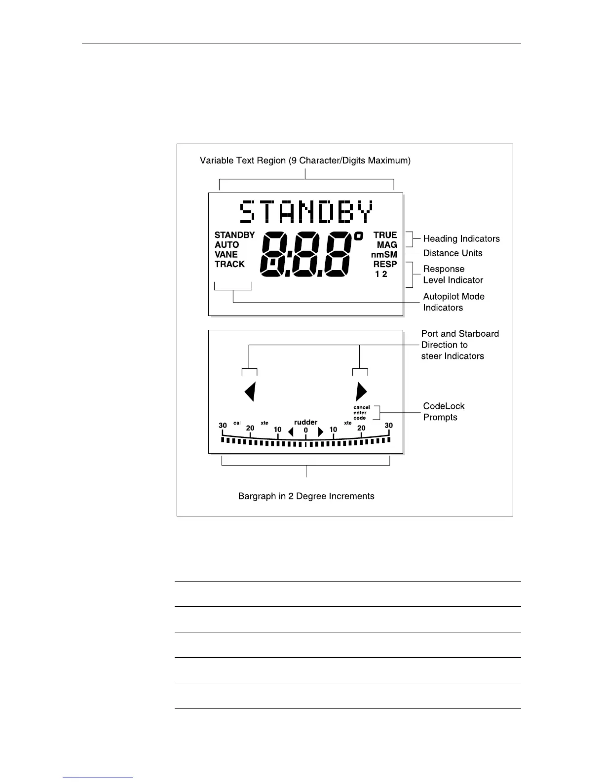
2.2 Display layout
The following illustration shows all the elements, together with a brief
description, that make up the ST6000 Plus autopilot LCD display.
Rudder or Steer Direction Indicator
D3507-1
MANUAL
3
The bar graph at the bottom of the display is normally a rudder bar.
If it has been set as a direction-to-steer indicator, the display depends
on the current mode, as follows:
Mode Bar
Standby Not used
Auto Heading error bar
Track Cross track error (XTE) bar, in 0.02 nm increments
Vane Wind angle error bar
If neither distance units (nm or SM) is displayed, the distance is
in Km.