25
References
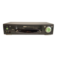
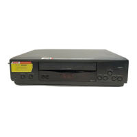
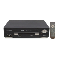
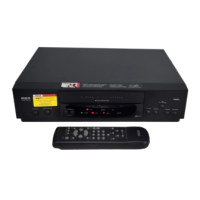
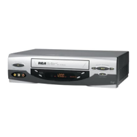
Location of Controls
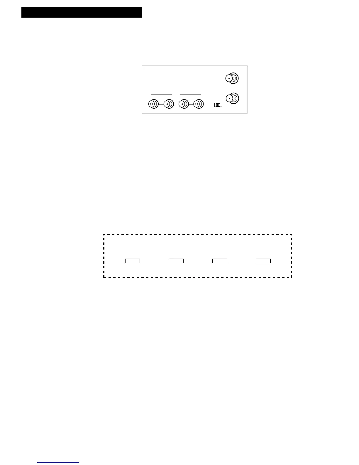
Back Panel
3CH.4 Switch
Selects the channel to which you tune the TV to
see the VCR picture if you connect the VCR
using one of the basic hookups.
IN FROM ANT. (Antenna) Connector
Receives a signal from an antenna or cable
system when attached.
OUT TO TV Connector
Passes signal to TV using the cable supplied.
VIDEO1 IN and AUDIO1 IN Jacks
Receives signals from another component, like a
VCR or camcorder, when it is connected to these
jacks. Use INPUT on the remote to select.
VIDEO1 OUT and AUDIO1 OUT Jacks
Sends signals from VCR to another component,
like a VCR or camcorder, when it is connected to
these jacks.
POWER Indicator
Lights when the VCR is turned on.
RECORD Indicator
Lights when the VCR is recording.
TIMER Indicator
Shows VCR is set for timer recording when
VCR is turned off.
Flashes when the clock is not set or a timer
recording is set and there is no cassette in
the VCR.
Display Panel
VCR Indicator
Lights when using the TV•VCR button.
When using one of the basic hookups:
• When VCR indicator is on, the picture comes
from the VCR.
• When VCR indicator is off, picture is from the
television channels.