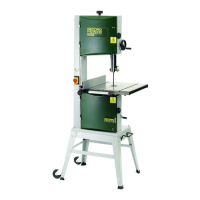
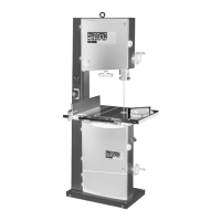
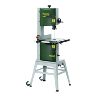
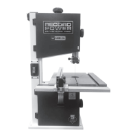
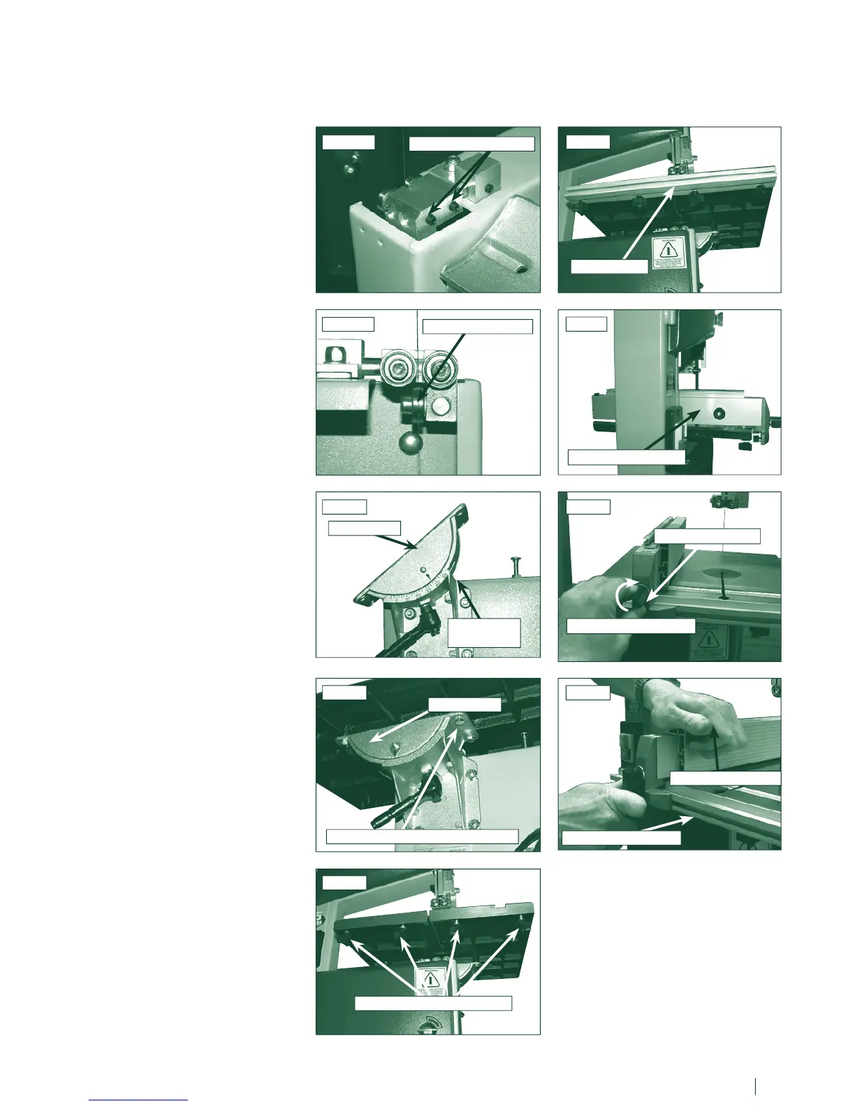
4. Machine Assembly - cont.
Fig.4.1B
THRUST BEARING
Fig.4.3
TRUNNION
TABLE FIXING BOLT & WASHER
12 13
At this stage it is advisable to make an
initial setting in the lower blade guides,
slacken the two left hand side grub
screws
Fig.4.1A, then position the guide
assembly so the blade runs centrally on
the thrust bearing
Fig.4.1B.
4.1 Fitting the table
Attach the trunnion to the trunnion carrier
with the ratchet handle supplied
Fig.4.2.
Adjust the trunnion until it is level and fit
the table using the four table bolts and
serrated was
hers Fig.4.3.
Caution
It may be necessary to seek
assistance with this as the table is
heavy and will not be stable until
bolted down.
4.2 Fitting the fence rail
Take the four star knobs and was
hers
and fit them into the threaded holes on
the underside of the table
Fig.4.4. But do
not fully tighten.
Slide the fence rail into the gap left
between the table and the star knobs
then tighten the star knobs to secure the
fence rail
Fig.4.5.
4.3 Fitting the rip fence
Slide the rip fence assembly onto the
fence rail and along the back of the table
Fig.4.6.
Pull down the locking lever to secure
the position, if the locking lever does
not lock the fence it can be adjusted by
rotating it clockwise this will enable the
fence to be locked securely
Fig.4.7.
Do not over tighten as this can damage
the cam. Tighten just enough to keep the
fence stable and secure.
Adjust this until you are happy with the
setting.
Tip
When locking the rip fence it is
advisable in place downward pressure
on the top of the fence
with one hand.
This ensures that the fence registers
correctly on the bottom flat of the
fence rail Fig.4.8.
Fig.4.4
Fig.4.5
Fig.4.6
Fig.4.7
Fig.4.8
Fig.4.1A
Fig.4.2
TRUNNION
TWO GRUB SCREWS
FENCE RAIL
STAR KNOBS & WASHERS
FENCE ASSEMBLY
LOCKING LEVER
APPLY PRESSURE
TRUNNION
CARRIER
BOTTOM FLAT RAIL
ROTATE TO TIGHTEN