16
Fig. 4.17
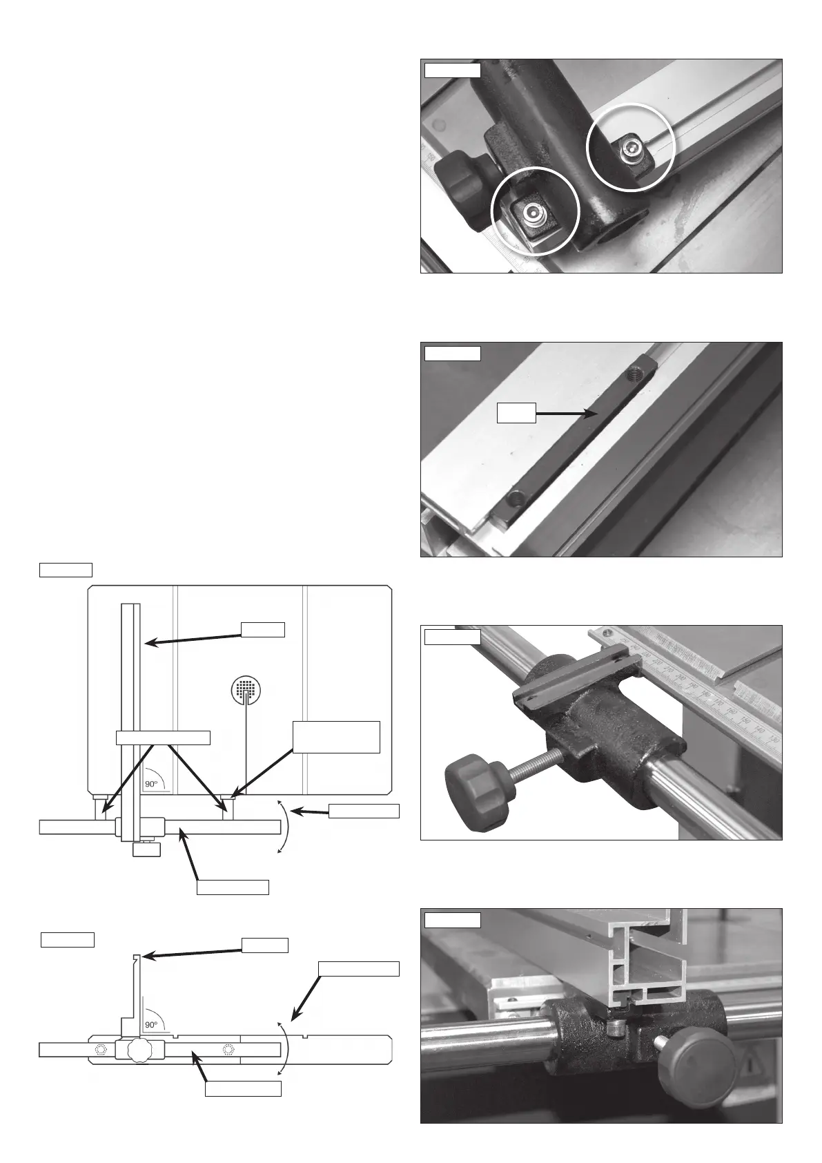
Fig. 4.18
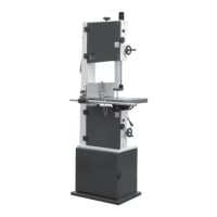
Fig. 4.15
Fig. 4.16
T-nut
4.9 Fitting the Fence
Remove the fence carrier from the fence extrusion using a 5 mm hex
wrench to remove the hex head socket screws and washers shown in
Fig. 4.15.
Ensure the T-nut on the underside of the fence as shown in Fig. 4.16
remains in place.
Slide the fence carrier onto the fence bar as shown in Fig. 4.17, ensuring it
is positioned to the left of the bandsaw blade.
Re-attach the fence extrusion as shown in Fig. 4.18.
4.10 Fence alignment 1
Align the fence assembly in or out until parallel with the mitre fence
slot (See Fig. 4.19) by turning the adjustment collars and the fence
bolts accordingly. If the fixing nuts have been tightened, these will need
slackening off before this adjustment can be made.
4.11 Fence alignment 2
Check that the fence is 90º to the table using a suitable square. If no
adjustment is needed, fully tighten the fence bar nuts. If adjustment is
required this is achieved by raising or lowering either side of the fence rail
until the fence itself is 90º to the table, (See Fig. 4.20). Once set at 90º
fully tighten the fence bar nuts.
4. Machine Assembly
Fig.4.20
FENCE
FENCE BAR
ADJUSTMENT
FENCE
FENCE BAR
MOVEMENT
ADJUSTMENT
COLLAR
FENCE BOLTS
Fig. 4.19