Control module STM 21 4
B6_Control_SYS20_EN_V1.3.doc Art. Nr. 102-020401135 21 / 36
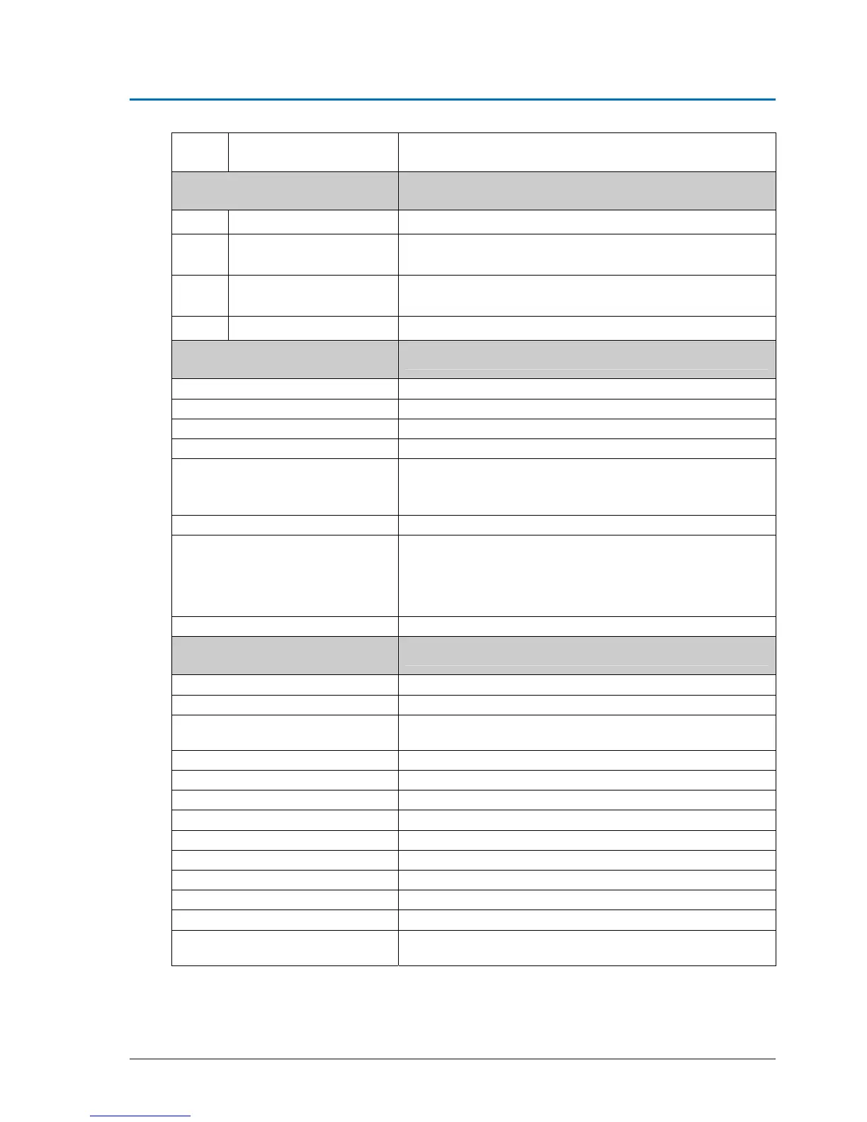
JP4
Standard D-ST & EST L
Re-plugging for monitoring devices EST R
– subsequently reboot of control necessary
Light-emitting diode Meaning
LD1
Red control-LED
For multifunctional key S1 – blinks when key is pressed
LD2
Red
Change plugging to reverse rotational direction (EST-R)
Then resetting STM is required
LD3
Green + 24 V
Is on, if 24 volt circuit OK
Comes off in case of by-pass in 24 volt circuit
LD4
Green + 32 V
Is on, if system connected to mains voltage
Multifunctional key
Function, after impulses have been given
1 puls
Activates an opening function (AKI)
2 pulses
Calibrating ELS
3 pulses
Calibrating door parameters
4 pulses
Entering programming level
5 pulses
Battery emergency reaction, as long as system is dis-
connected from mains
Battery test in case of mains connection
8 pulses
Loads default values of door type selected
9 pulses
Back to factory settings
(afterwards an emergency stop or a reset must be actuated
within 10 seconds) The function emergency-stop with reset
can only be actuated if the INPUT/OUTPUT parameter
Emergency-Stop with Reset is active!!
14 pulses
Hardware reset is performed within ca. 12 seconds
Connector designation
Connections
J1
Mains plug
J2
Terminals 25 – 28 für BDE-D
J3
Terminals 1 - 12:
Functions according to wiring diagram 021.110.649_D
J4
Locking device
J5
Battery
J6
Motor brake
J7
ATE Motor
J8
CAN-bus
J9
CAN bus plug for FPC-servicing
J10
Encoder motor
J11
Extra printed circuit board ELS (ZLP-ELS)
J12 - 13
Reserved for future modules
J15
Extra printed circuit board BAT (ZLP-BAT) for lead-acid bat-
tery