Control module STM 20 2
B6_Control_SYS20_EN_V1.3.doc Art. Nr. 102-020401135 7 / 36
2. Control module STM 20
2.1. Controlling elements on STM 20
Control module STM 20 works with an active HIGH level. That means that a minimum of +24V is
required to activate a function. Safety functions of inputs are activated in case of interruption. 0V is
connected to the ground. This connection can be interrupted for test reasons by use of the ground
screw, located next to terminal 12. LED 2 (red) comes on.
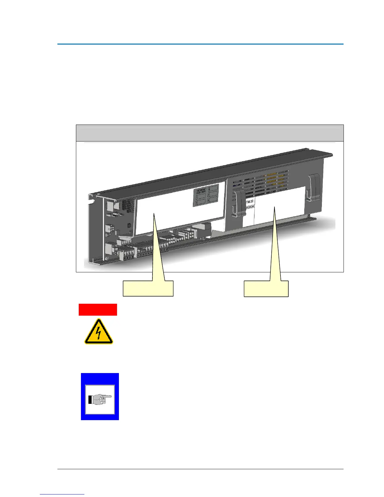
Control module and power supply
ELECTRIC SHOCK
Electric shock, combustion, death when touching the power supply without
protection cover
Before opening the metallic cover of the power supply unit, disconnect it
from the mains
The installation may only be connected to the mains again, after the protec-
tion cover has been closed again
The STM 20 control module has been tested after ISO standard 13849-1:2006,
category 2 PLc.
NOTE
Control module
STM 20
Fused power
su