Control module STM 20 2
B6_Control_SYS20_EN_V1.3.doc Art. Nr. 102-020401135 8 / 36
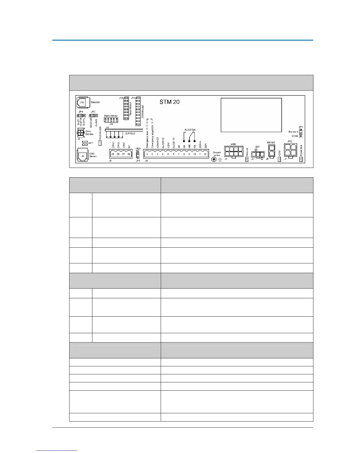
2.2. Type plate STM 20
STM20
Jumper Change of function
JP1
Jumper on HEA
Allows emergency stop and HEA to be connected in series:
HEA 3-2
Emergency stop 2-1
JP2
Standard / CO48
Influences motor-driven braking function in case of power
failure
(weaker with CO48)
JP3
Syst.-conditioned, internal Not visible – reserved for future applications
JP4
Standard D-ST & EST L
Change plugging to reverse rotational direction (EST-R)
– The resetting of the control is required
JP5
Standard master mode Slave – only in case of two STM
Light-emitting diode Meaning
LD1
Red control-LED
For MF button S1 – blinking, when button is pressed
LD2
Ground – Red control-
LED
Must light up, if protective earth screw is withdrawn
Otherwise grounding is on
LD3
green + 24 V
Is on, if 24 volt circuit is OK
Comes off in case of short-circuit in 24 volt
LD4
green + 32 V
Is on, if system connected to mains voltage
Multifunctional key Function, after impulses have been given
1 pulse
Releases an opening movement (AKI)
2 pulses
Calibrating ELS
3 pulses
Calibrating door parameters
4 pulses
Entering programming level
5 pulses
Battery emergency reaction, as long as system is discon-
nected from mains
Battery test in case of mains connection
8 pulses
Loads default values of door type selected