Control module STM 21 RED 5
B6_Control_SYS20_EN_V1.3.doc Art. Nr. 102-020401135 25 / 36
5.2.1. Escape and rescue routes as RED installation
Control module STM 21 RED with RED software has been tested according
EN 13849-1:2006, category 3 PLd.
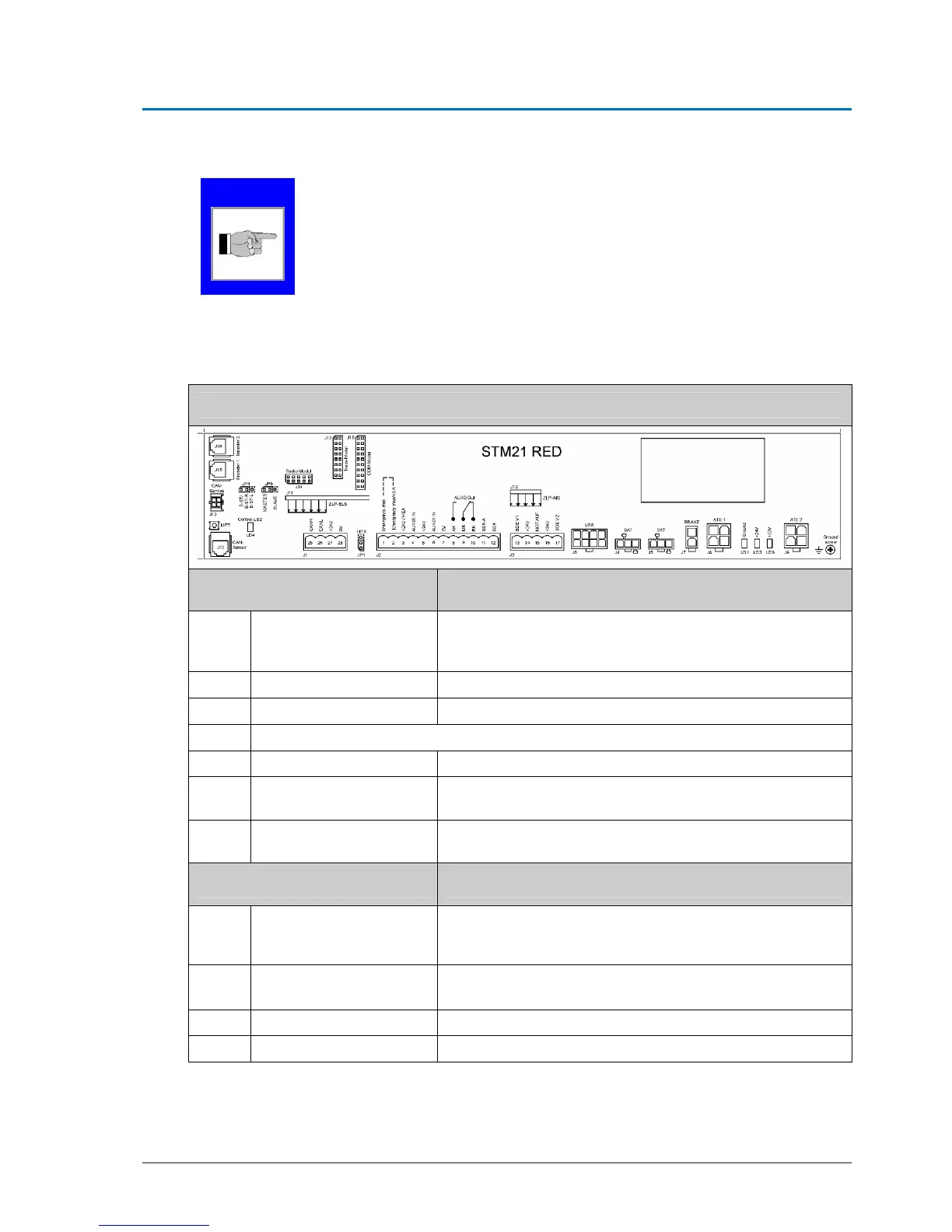
5.3. Type plate STM 21 RED
STM 21 RED
Jumper Change of function
JP1
Jumper on HEA
Allows emergency stop and HEA to be connected in series
HEA 3-2
Emergency stop 2-1
JP2
Not printed
JP3
Syst.-conditioned, internal Not visible – required for VRR2 (MPV 16)
JP4 On RED and DUO installation
D-ST & EST-R Factory setting
EST-L
Fixing connecting clamp to upper part of toothed belt - Shunt
position remains unchanged !
JP5
Standard Master opera-
tion mode
Slave – only in case of two STM
Light-emitting diodes Meaning
LD1
Ground – red control-LED
Ground – must light up, if protective earth screw is with-
drawn
Otherwise grounding is on
LD2
green + 24 V
Is on, if 24 volt circuit OK
Comes off in case of by-pass in 24 volt circuit
LD3
green + 32 V
Is on, if system connected to mains voltage
LD4
red control-LED
For MF key S1 – is blinking, if button is pressed
NOTE