Installation, Operation and Technical Manual Rectifier Technologies
158-1872-01 22 19-Feb-14
4.5.3.2 Relay Contact outputs
There are 5 relays with normally open (N/O) and normally closed (N/C) contacts available
on the MUIB3, connector X2. In standard RTP system three of the relays are for remote
annunciation of alarms: Relay 3 - HVSD, Relay 4 - any system alarm, Relay 5 - SMR shut
down.
Other two relays are used for control of optional external equipment.
Relay 2 is programmed for FAN CONTROL. If any one of the SMR heat-sink temperatures
exceeds a pre-set (non-programmable) value, the relay closes. The relay closure can then
be used to either speed up fans, which may normally be idling at low speed, or it can turn
on fans, which may normally be off.
In 110V systems Relay 1 closes during battery discharge test, allowing control of dummy
load on standby systems. In 24V and 48V systems it has no assigned function.
If MCSU-4 supports User Programmable Relays, the functions described above can be
changed on site according to specification of the installation (for details see paragraph
“User programmable relay functions” in chapter “Operation”). It is also possible to
permanently assign different functions to the relays on end user request by modifying
controller software.
4.5.3.3 Spare Digital Inputs
There are 4 spare digital inputs (USER 1, 2, 3, 4) available on the MUIB3 for the
monitoring of external plant associated with the power supply. The inputs must be isolated
relay contacts or auxiliary contacts which are either normally open or normally closed. The
MCSU-4 software for monitoring of the inputs must be user defined.
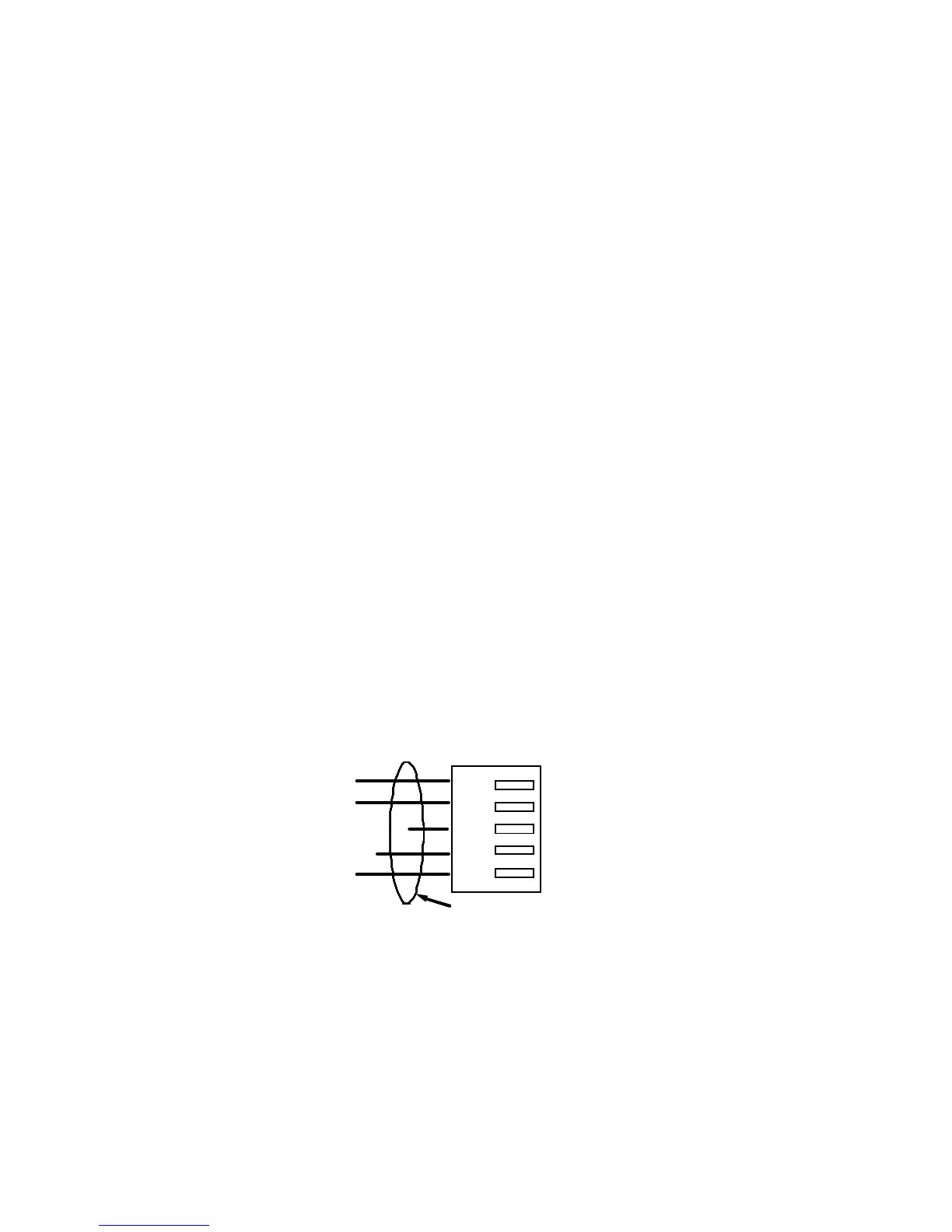
4.5.3.4 Battery Current Transducer Input
Battery current transducers are connected to X39 and X40 of the MUIB3. Current
transducers come in several connection configurations, but below are the pin connections
for the battery transducer connector going onto the MUIB3:
Figure 4.5-1 Current transducer connection
4.5.3.5 Power Input
Power to the MCSU-4 comes from the DC bus via connector X50. Pin designations are
labelled on the PCB. The system voltage is also read by the MCSU-4 via this connector.
4.5.3.6 CB Trip and Batt Sw inputs
CB Trip (X22) is used to sense the CB status. Batt Sw (X23) is used to sense the battery
switch status. Open contacts on any of these 2 inputs creates an alarm condition on the