Installation, Operation and Technical Manual Rectifier Technologies
158-1872-01 23 19-Feb-14
MCSU-4. Therefore, when any one of these 2 inputs are not used, a shorting plug should
be installed on the input not being used.
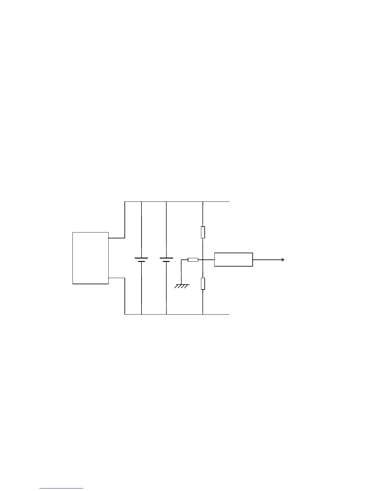
4.5.3.7 Earth Leakage Detector
The block diagram in Figure 4.5-2 shows the principle on which the earth leakage detector
works. The SMRs and Batteries, which are normally galvanically isolated from Earth, are
actually grounded via sensing resistor Rde which connects to the centre-tap of two
relatively high value resistors (Re in Figure 4.5-2). The effect is that if there are no other
electrical paths to Earth, then +Vb and -Vb should be equal and opposite in value. So if
the battery voltage, for example, is 124VDC, the voltage of the positive DC bus with
respect to Earth should be +62VDC and the negative bus should be -62VDC.
If there is any external leakage path to Earth (e.g. battery acid trickles to metal, earthed
frame), the return path must be through Rde. The voltage developed will then be
measured and interpreted by the microprocessor in the MCSU-4.
It should be noted that if there is no external leakage current, the voltage measured at the
test point on the UIB3 marked ELEAK will not be zero, but a calibrated voltage a little over
2.5VDC. This is an offset voltage, which has been introduced to enable the
microprocessor to monitor earth leakage current of both positive and negative polarity.