Installation, Operation and Technical Manual Rectifier Technologies
158-1872-01 80 19-Feb-14
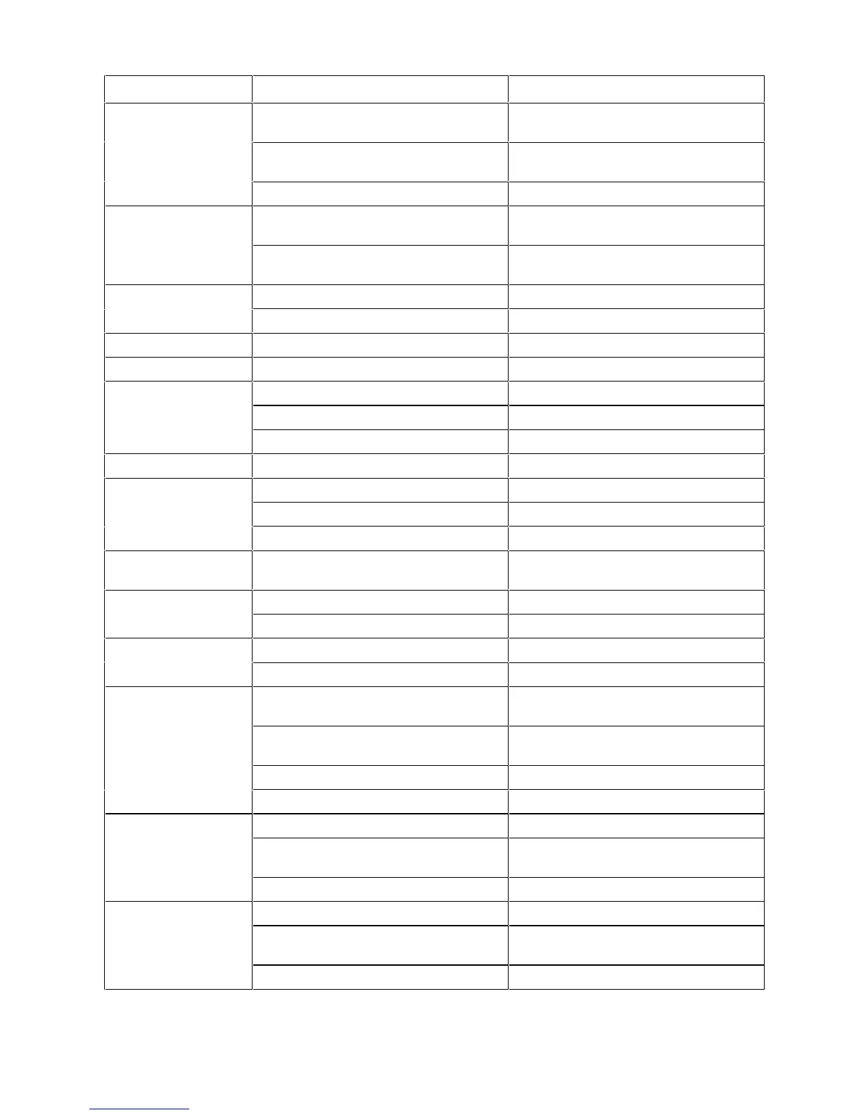
Load circuit breakers have tripped and
there is no load
If only one unit showing alarm, comms
line to SMR may be faulty
In SMR menu check status of this SMR.
If “No Response” replace comms line
Batteries being recharged if more than
one unit showing alarm
If only one unit shows alarm, internal
control loop faulty
Internal control loop faulty
Faulty EEPROM or microprocessor card
SMR Heat sink temperature too high
Check air intake to SMR is not blocked
Ambient temperature is too high
Try to reduce ambient temperature
Microprocessor card is faulty
Temperature sensor is faulty
Fan Fail
(Fan cooled nits only)
Air flow inadequate due to dirty filter
Air intake/outlet blocked
Replace fan if connection is OK
Reference voltage source in, or entire
microprocessor card is faulty
Inrush limiting fuse or resistor O/C
Feedback voltage circuit faulty
Faulty microprocessor card
Battery discharged to the limit voltage
level due to no AC power
Check AC voltage and reset if possible
In BATT menu check if LVDS mode is
set to “Open”.
Battery voltage OK, MCSU-4 faulty
LVDS threshold level set too high
Volts High level in MCSU-4 set too low
Reset level to correct value
Temperature compensation coefficient
set too high
Set correct temperature compensation
coefficient
Volts Low threshold in MCSU-4 too high
Reset level to correct value
Temperature compensation coefficient
set too high
Set correct temperature compensation
coefficient