-12-
Drawing No. LP0932 Released 2018-01-12
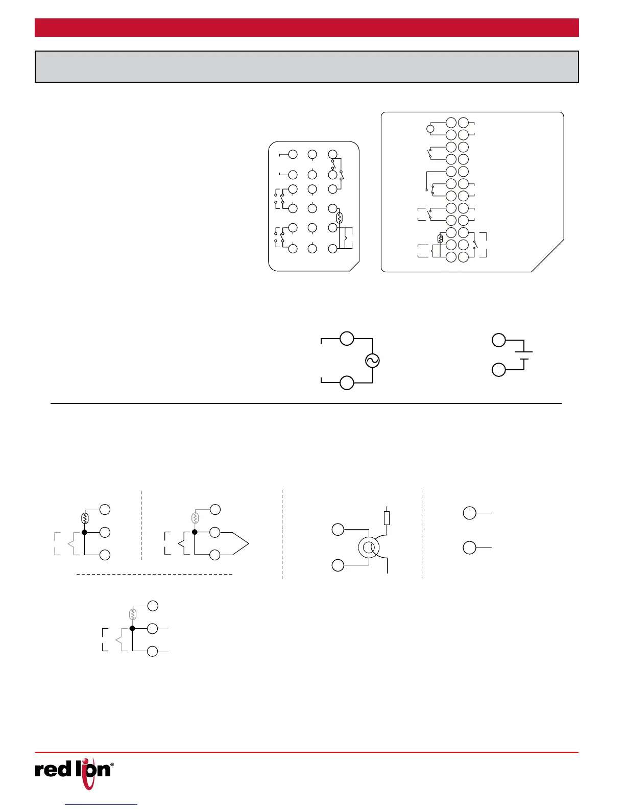
All wiring connections are made to the rear screw
terminals. When wiring the controller, use the numbers on
the label and those embossed on the back of the case, to
identify the position number with the proper function.
All conductors should meet voltage and current ratings
for each terminal. Also, cabling should conform to
appropriate standards of good installation, local codes and
regulations. It is recommended that power (AC or DC)
supplied to the controller be protected by a fuse or circuit
breaker. Strip the wire, leaving approximately 1/4" (6 mm)
bare wire exposed (stranded wires should be tinned with
solder). Insert the wire under the clamping washer and
tighten the screw until the wire is clamped tightly.
1
L
50/60 Hz
5VA
AC 100~240V
N
2
13
14
User 1/CT1/Remote
8
7
+
-
15 93
User 2/Retrans
41016
AL1
AL2
OP 2/ AL 3
+
-
11175
12186
RTD
OP 1RS-485
D
D
-
+
+
IN
Tc
+
--
+
-
-
+
AC 100~240V
50/60 Hz
5VA
1
~
13
2
14
3
15
4
16
5
17
618
7
19
8
20
921
10 22
11 23
12 24
IN
Tc
NO
D-
L
N
NO
D+
RS-485
NO
NO
&200
&200
&200
&200
NC
AL 1
AL 2
OP 1
User 2/Retrans
User 1/CT1/Remote
OP 2/ AL 3
+
++
+
+
+
-
-
-
-
-
-
-
+
+
-
+
-
+
-
1/16 DIN 1/8 or 1/4 DIN
For best results, the power should be relatively “clean” and
within the specified limits. Drawing power from heavily loaded
circuits or from circuits that also power loads that cycle on and
off should be avoided. It is recommended that power supplied
to the controller be protected by a fuse or circuit breaker.
2
1
C 100-240V
50/60 Hz
5VA
For two wire RTDs, install a copper sense lead of the same gauge and
length as the RTD leads. Attach one end of the wire at the probe and the
other end to input common terminal. This is the preferred method as it
provides complete lead wire compensation. If a sense wire is not used,
then use a jumper. A temperature offset error will exist. The error may be
compensated by programming a temperature offset.
0 V
24V AC/DC
2
1
+
AC power terminal labels shown.
See below for DC power terminal
label. All other terminals are identical
between AC and DC powered units.
12
11
10
IN
T
C
+
-
+
-
RTD
TC-
TC+
IN
T
C
+
-
+
-
12
11
10
DC+ VOLTAGE/CURREN
DC- VOLTAGE/CURRENT
IN
T
C
+
-
+
-
12
11
10
USER 1/CT1/REMOTE
LOAD
+
-
-
+
USER 1/CT1/REMOTE
+
-
-
+
DC- VOLTAGE/CURRENT
DC+ VOLTAGE/CURRENT
* Reference unit label for terminal number.
 Loading...
