-18-
Drawing No. LP0932 Released 2018-01-12
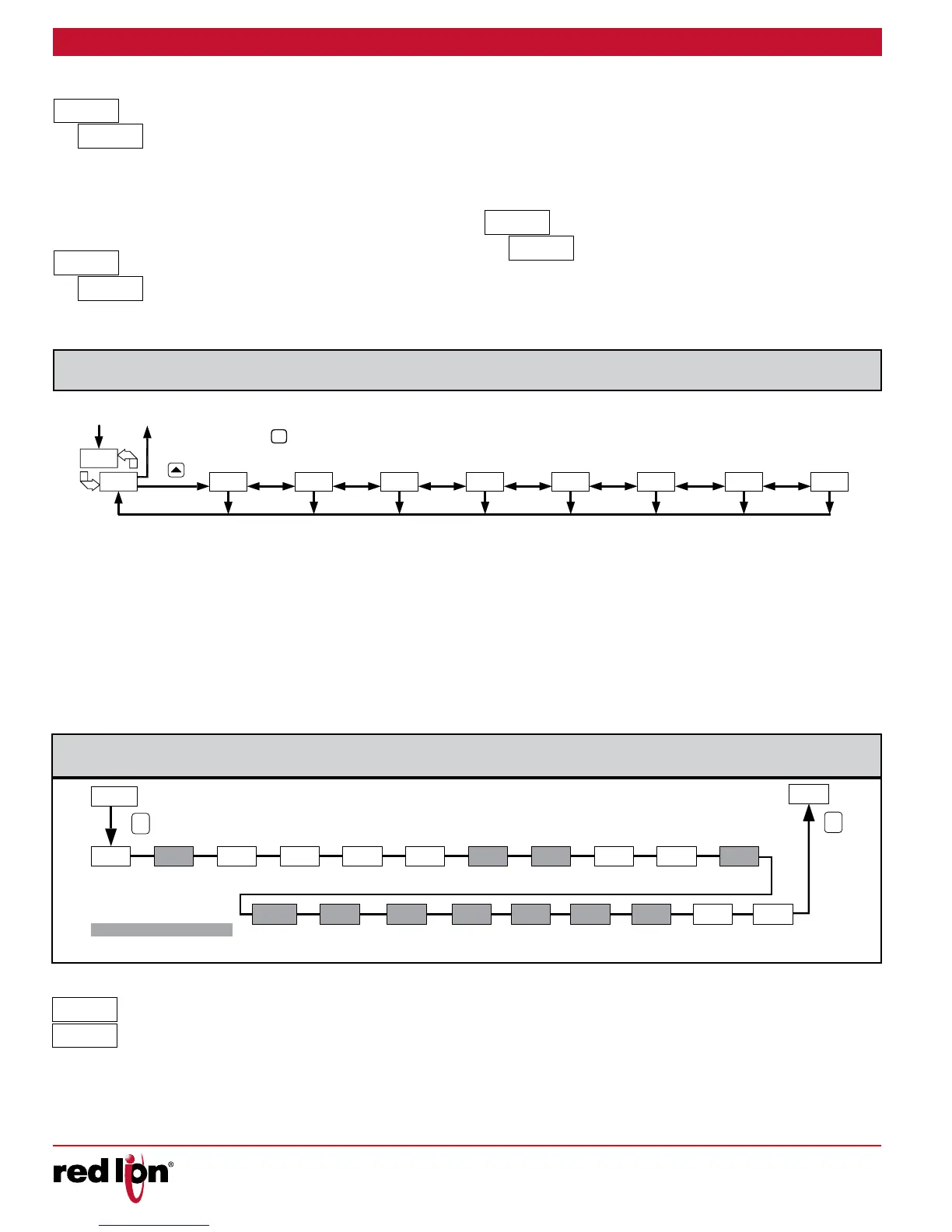
LOOP
HIDDENDISPLAY
LOOP
PARAMETERS
INPUT
MODULE MODULE
OUTPUT
PARAMETERS
LOCKOUT
PARAMETERS
MODULE
COMMUNICATION
PARAMETERS
MODULE
ALARM
PARAMETERS
MODULE
FACTOR
SERVICE
MODULE
CONTROL
PARAMETERS
MODULE
PROFILE
MODULE
P
To access the Configuration Loop, press the up key when CNFP/NO is
displayed in the Hidden Loop. In the Configuration Loop, CNFP will
alternate with the parameter number in the bottom display and the
Temperature/Process Value is shown on the top display. The arrow keys
are used to select the parameter module (1-9). To enter a specific
module press : while the module number is displayed. In the
Configuration Loop, CNFP will alternate with the parameter number in the
bottom display and the Temperature/Process Value is shown on the top
display.
After entering a parameter module, press : to advance through the
parameters in the module. To change a parameter’s selection/value,
press the arrow keys while the parameter is displayed. In the modules,
the top display shows the parameter name, and the bottom display
shows the selection/value. Use : to enter and store the selection/value
that has been changed. If a power loss occurs before returning to the
Display Loop, the new values should be checked for accuracy.
At the end of each module, the controller returns to CNFP/NO. At this
location, pressing : again returns the display to the the Display Loop.
Pressing the B key allows re-entrance to the Configuration Loop.
Whenever = is pressed, nd momentarily appears, the current parameter
change will be aborted, and the controller returns to the Display Loop.
1-IN
INPUT
TYPE
TEMP
SCALE
DECIMAL
RESOLUTION
DIGITAL
FILTERING BAND
FILTER
VALUE 1
DISPLAYSHIFT/
OFFSET
VALUE 2
DISPLAY
SETPOINT
LOW LIMIT
SETPOINT
HIGH LIMIT
REMOTE
INPUT TYPE
P
P
INPUT 1
USER
USER
INPUT 2
FUNCTION
F1 KEY
F2 KEY
FUNCTION
COLD
JUNCTION
REMOTE
SETPOINT
RATIO MULTIPLIER
REMOTE
SETPOINT
BIAS
REMOTE INPUT
HIGH DISPLAY
REMOTE INPUT
LOW DISPLAY
Programming/model dependent.
Select the input type that corresponds to the input sensor.
SELECTION TYPE SELECTION TYPE
-k
K TC
k
TXK TC
-J
J TC
r392
RTD 392
-
T TC
r35
RTD 385
-
E TC
nI
RTD 672
-N
N TC
Cu 50
-r
R TC
u
0-5 Volt
-J
YP
P
P
P ProF RMO
Select Setpoint, Profile control, or Remote. Setpoint mode selection
results in the controller controlling to the active setpoint. Profile mode
selection results in the controller controlling to the active profile. Remote
selection results in the controller controlling to the remote input setpoint.
Auo
rnF
Auo r
In Automatic Mode (Auo), the percentage of Output Power is
automatically determined by the controller based on the Auto Control
SELECTION TYPE SELECTION TYPE
-
S TC
10u
0-10 Volt
-b
B TC
0-20
0-20 mA
-L
L TC
4-20
4-20 mA
-
U TC
0.05u
0-50 mV
Mode selected. In Manual/User Mode (r), the percentage of Output
Power is adjusted manually by the user. The Control Mode can also be
transferred through the 1 or 2 key or User Input. For more information,
see Control Mode Explanations.
dV
Setpoint deviation is the number of display units that the input display
varies from the active setpoint value. This is a read only value.
 Loading...
