-8-
Drawing No. LP0932 Released 2018-01-12
1. DISPLAY: LCD negative image transmissive with backlighting. Top
(process) display with orange backlighting, bottom (parameter) display
with green backlighting.
Line 1 and 2: 4 digits each line
Status Annunciators:
OUT1 - Control output 1 is active.
OUT2 - Control output 2 is active.
ALM1 - Alarm 1 output is active.
ALM2 - Alarm 2 output is active.
ALM3 - Alarm 3 output is active.
°F, °C - Temperature units.
MAN - Controller is in Manual Mode.
REMOTE - Controller is in Remote Setpoint Mode.
AT - Auto-Tune active.
1/16 DIN Model Digit Size: Line 1 - 0.43" (11 mm); Line 2 - 0.27" (7.0 mm)
1/8 DIN Model Digit Size: Line 1 - 0.47” (12 mm); Line 2 - 0.47” (12 mm)
1/4 DIN Model Digit Size: Line 1 - 0.87" (22 mm); Line 2 - 0.55" (14 mm)
2. POWER:
Line Voltage Models:
100 to 240 VAC -20/+8 %, 50/60 Hz, 5 VA
Low Voltage Models:
AC Power: 24 VAC, ± 10%, 6 VA
DC Power: 24 VDC, ±10%, 8 VA
3. KEYPAD: Mylar overlay with 4 program/selection keys and 2 user
programmable function keys. 6 keys total.
4. Display Messages:
OLOL - Measurement exceeds + sensor range
LL - Measurement exceeds - sensor range
OPN - Open sensor is detected (TC or RTD)
r - Shorted sensor is detected (RTD only)
. . . - Display value exceeds + display range
-. .. . - Display value exceeds - display range
5. SETPOINT PROFILE:
Profiles: 16
Segments per Profile: 16 ramp or hold segments (linkable up to 256
segments).
Segment Time: 0 to 999.9 or 9999 minutes; can be extended by linking.
Error Band Conformity: Delays profile progress; Off or from 1 to
9999 process unit’s deviation,
Program Auto Cycle: 0 to 250, 0 = continuous.
Setpoint Profile Selection/Control: Front panel buttons, user input,
or MODBUS communications.
6. CONTROL SETS:
Setpoints: 6, SP1-SP6
Control Sets: 6, PID 1-6
PID Gain Sets: 6, PID 1-6; includes PID constants
7. SENSOR INPUT:
Sample Period: 100 msec (10 Hz rate)
A/D Converter: 16 bit resolution
Span Drift (maximum): 130 PPM/°C
Input Fail Response:
Main Control Output(s): Programmable preset output
Display: OPN, r
Alarms: programmable for ON or OFF
Normal Mode Rejection: >35 dB @ 50/60 Hz
Common Mode Rejection: >120 dB, DC to 60 Hz
8. INPUT CAPABILITIES:
Temperature/RTD Indication Accuracy:
± (0.3% of span, +1 °C) at 25 °C ambient after 20 minute warm up.
Includes NIST conformity, cold junction effect, A/D conversion
errors and linearization conformity.
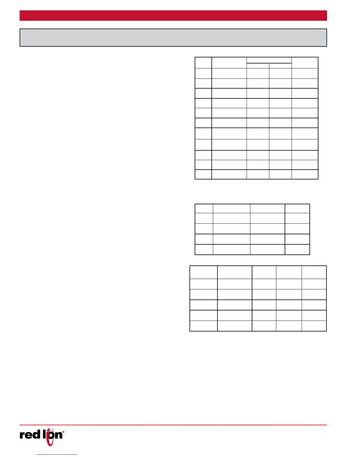
THERMOCOUPLE INPUTS:
Types: T, E, J, K, R, S, B, N, L, U, and TXK
Input Impedance: Approximately 4.7 MΩ
Lead Resistance Effect: -0.3 µV/Ω
Cold Junction Compensation: Less than ±1.5 °C typical (2.5 °C
max) error over 0 to 50 °C temperature range.
Resolution: 1° for types R, S, B and 1° or 0.1° for all other types
TYPE DISPLAY RANGE
WIRE COLOR
STANDARD
ANSI BS 1843
T
-200 to +400 °C
-328 to +752 °F
(+) Blue
(-) Red
(+) White
(-) Blue
ITS-90
E
0 to 600 °C
+32 to +1112 °F
(+) Violet
(-) Red
(+) Brown
(-) Blue
ITS-90
J
-100 to +1200 °C
-148 to +2192 °F
(+) White
(-) Red
(+) Yellow
(-) Blue
ITS-90
K
-200 to +1300 °C
-328 to +2372 °F
(+) Yellow
(-) Red
(+) Brown
(-) Blue
ITS-90
R
0 to +1700 °C
+32 to +3092 °F
No
standard
(+) White
(-) Blue
ITS-90
S
0 to +1700 °C
+32 to +3092 °F
No
standard
(+) White
(-) Blue
ITS-90
B
+100 to +1800 °C
+212 to +3272 °F
No
standard
No
standard
ITS-90
N
-200 to +1300 °C
-328 to +2372 °F
(+) Orange
(-) Red
(+) Orange
(-) Blue
ITS-90
L
-200 to +850 °C
-328 to +1562 °F
(+) Red
(-) Blue
(+) Red
(-) Blue
DIN 43714
U
-200 to +500 °C
-328 to +932 °F
No
standard
(+) White
(-) Blue
IPTS68
TXK
-200 to +800 °C
-328 to +1472 °F
— — —
RTD INPUTS:
Type: 2 or 3 wire
Excitation: 180 µA typical
Resolution: 1° or 0.1° for all types
TYPE INPUT TYPE RANGE STANDARD
385
100 Ω platinum,
Alpha = .00385
-200 to +850 °C
-328 to +1562 °F
IEC 751
392
100 Ω platinum,
Alpha = .003919
-20 to +400 °C
-32 to +752 °F
No official
standard
672
120 Ω Nickel
alpha = .00672
-80 to +300 °C
-112 to +572 °F
Cu50
50 Ω Copper
alpha = .00428
-50 to +150 °C
-58 to +302 °F
PROCESS INPUTS:
INPUT RANGE ACCURACY * IMPEDANCE
MAX
CONTINUOUS
OVERLOAD
RESOLUTION
0-5 VDC
0.3% of rdg
+ 0.03 V
1.8 MW
50 V 395 µV
0-10 VDC
0.3% of rdg
+ 0.03 V
1.8 MW
50 V 395 µV
0-20 mA
0.3% of rdg
+ 0.04 mA
249 W
30 mA 1.6 µA
4-20 mA
0.3% of rdg
+ 0.04 mA
249 W
30 mA 1.6 µA
0-50 mV
0.3% of rdg
+ 0.1 mV
4.7 MW
30 V 2.2 µV
*Accuracies are expressed as ± percentages @ 25 °C ambient range
after 20 minute warm-up.
CT INPUT (Optional): CT is included with this option
Type: Single phase, full wave monitoring of load currents
Input: 0 to 25 mA AC
Display Scale Range: 1.0 to 999.9 amperes
Input Impedence: 10 W @ 50/60 Hz
Frequency: 50/60 Hz
Maximum Continuous Overload: 31 mA AC
CT Rating
Current Ratio: 40 A/30.7 mA AC
Turn Ratio: 1:1300
 Loading...
