— English Servitec 35-95 with
— 18.12.2019 - Rev. A
6.5 Electrical connection
Risk of serious injury or death due to electric shock.
If live parts are touched, there is risk of life-threatening injuries.
• Ensure that the system is voltage-free before installing the device.
• Ensure that the system is secured and cannot be reactivated by other
persons.
• Ensure that installation work for the electric connection of the device is
carried out by an electrician, and in compliance with electrical engineering
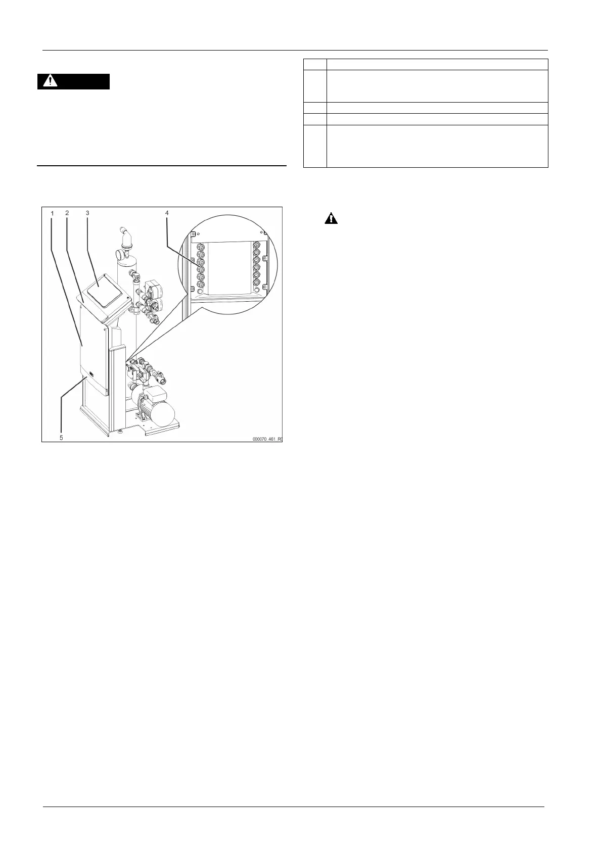
For the electrical connection, you must differentiate between a connection
component and an operating component.
1 Connection unit
2 Covers of the operating unit (folding)
• RS-485 interfaces
• Pressure output
3 Operating unit (Control Touch controller)
4 Cable bushings
5 Covers of the connection unit (folding)
• Supply and fusing
• Floating contacts
• Aggregate connection
The following descriptions apply to standard systems and are limited to the
necessary user-provided connections.
1. Shut down the system and secure it against unintentional reactivation.
2. Remove the covers.
DANGER – electric shock! Risk of serious injury or death due to electric
shock. Some parts of the device's circuit board may still be live with 230 V
even after the device has been physically isolated from the power supply
by pulling out of the mains plug. Before you remove the covers, completely
isolate the device controller from the power supply. Verify that the main
circuit board is voltage-free.
3. Insert a suitable screwed cable gland for the cable bushings at the rear of
the connection component. M16 or M20, for example.
4. Thread all cables to be connected through the cable glands.
5. Connect all cables as shown in the terminal diagrams.
– Connection unit, see chapter 6.5.1 "Terminal plan, connection
component" on page 11 .
– Operating unit, see chapter 6.5.2 "Terminal plan, operating unit" on
page 12 .
– When providing fusing for the appliance, note its connected load, see
chapter 5 "Technical data" on page 6 .
6. Install the cover.
7. Connect the mains plug to the 230 V power supply.
8. Activate the system.
The electrical connection is completed.