Servitec 35-95 with
— 18.12.2019 - Rev. A
English —
The maintenance schedule is a summary of maintenance tasks to be carried out
regularly.
▲ = Check, ■ = Service, ● = Clean
Check for leaks, see chapter 10.1
"Exterior leak test" on page 23 .
• "PU" pump
• Screw connections
• "DV" degassing valve
Annually
Vacuum function test.
– see chapter 7.8 "Vacuum test" on
page 15
Annually
Clean the dirt trap.
– see chapter 10.2 "Cleaning the
dirt trap" on page 23
Depending on
the operating
conditions
Check the controller settings.
Annually
Function test.
• "SE" system degassing
• Make-up degassing "NE"
see chapter 10.3 "Function test"
on page 23
Annually
When operating with water/glycol
mixtures
• Control of the mixing ratio.
• If necessary, adjust according to
manufacturer information.
Annually
10.1 Exterior leak test
Check the following Servitec components for leaks:
• Pump
• Screw connections
• Degassing valves
Proceed as follows:
• Seal any leaks at the connections or replace the connections, if required.
• Seal leaking screw connections or replace, if required.
10.2 Cleaning the dirt trap
Risk of injury due to pressurised liquid
If installation, removal or maintenance work is not carried out correctly, there is a
risk of burns and other injuries at the connection points, if pressurised hot water
or hot steam suddenly escapes.
• Ensure proper installation, removal or maintenance work.
• Ensure that the system is de-pressurised before performing installation,
removal or maintenance work at the connection points.
The "ST" dirt trap in the "DC" degassing line must be cleaned no later than after
the continuous degassing time has elapsed. Check the dirt traps after every
filling action or extended operation.
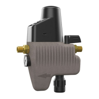
1 "ST" dirt trap
1. Press "Stop" on the controller's operator panel.
– The Servitec is non-functioning and the "PU" pump is shut down.
2. Close the ball valve upstream of the "ST" (1) dirt trap.
3. Slowly unscrew the cap with the dirt trap insert at the dirt trap to release
any residual pressure in the pipeline section.
4. Pull the mesh from the cap and rinse it with clear water. Use a soft brush
for cleaning.
5. Re-insert the mesh into the cap, check the gasket for damage, and screw
the cap back into the housing of the "ST" (1) dirt trap.
6. Open the ball valve upstream of the "ST" (1) dirt trap.
7. Press "Auto" on the controller's operator panel.
– The Servitec is switched on and the "PU" pump is in operation.
Note!
Clean all other installed dirt traps (in the Fillset, for example).
10.3 Function test
Check in sequence the degassing of facility water and make-up water.
Proceed as follows:
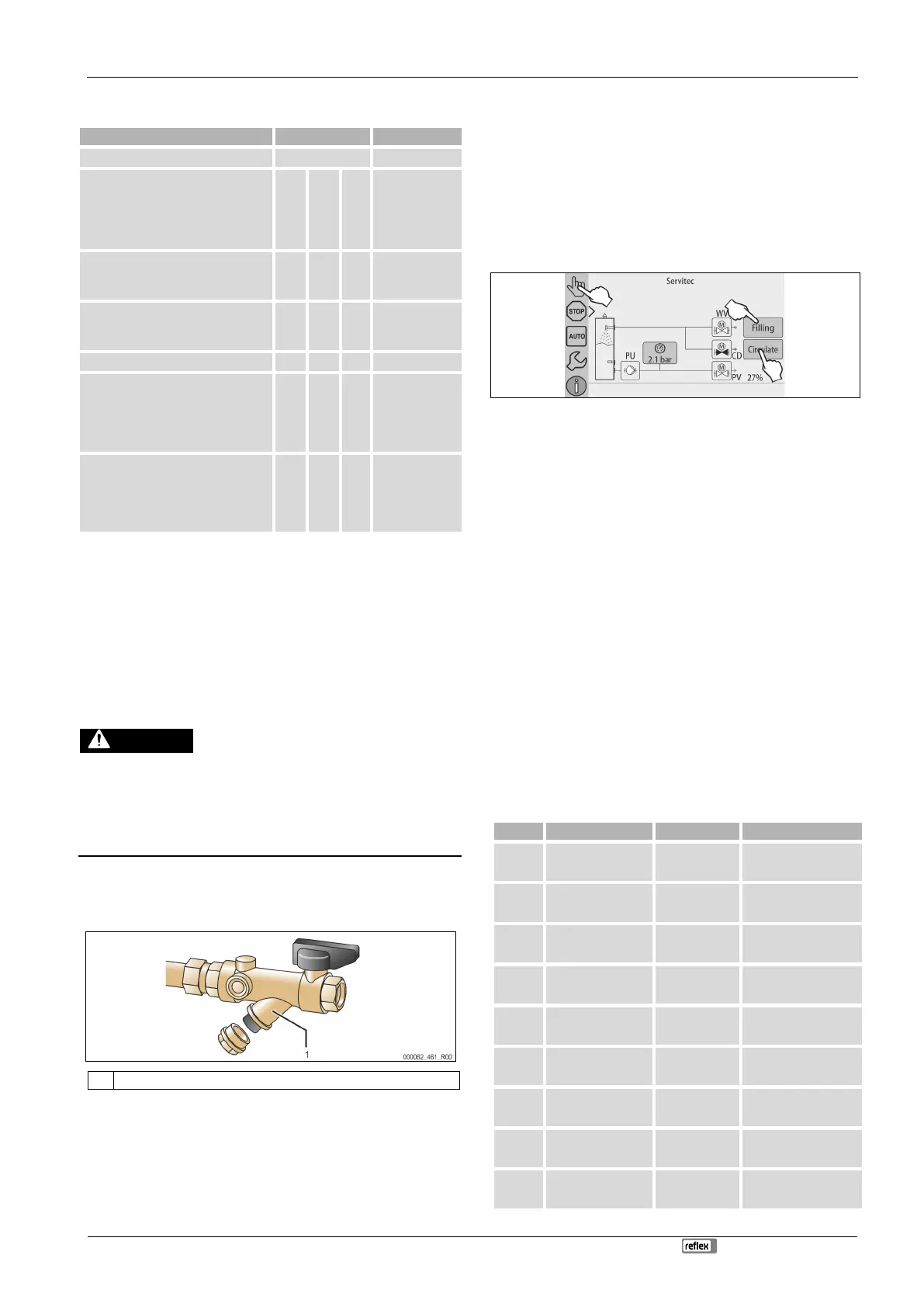
1. Switch to Manual mode, see chapter 8.1.2 "Manual mode" on page 17 .
2. Run 10 cycles for facility water degassing.
– To degas the facility water, touch "Circulate". The "Circulate" function
activates the continuous degassing of facility water.
3. Run 10 cycles for make-up water degassing.
– To degas the make-up water, touch "Fill". The "Fill" function activates
the continuous degassing of make-up water.
Note!
The gas must be eliminated from the d
evice before the next interval
After the cycles are completed, a saturation pressure is present. With cold water,
the "PI" vacuum gauge must eventually show a value of approx. -1 bar.
4. Press "AUTO" to deactivate Manual mode.
– Automatic mode is activated.
The inspection of the degassing is concluded.
Note!
The "Insufficient water" message must not be displayed at the
controller.
10.4 Maintenance certificate
All maintenance tasks have been completed according to the Reflex Installation,
Operating and Maintenance Manual.