— English Servitec 35-95 with
— 18.12.2019 - Rev. A
Note!
During installation, pay attention to the operability of the valves and the
inlet options for the connecting lines.
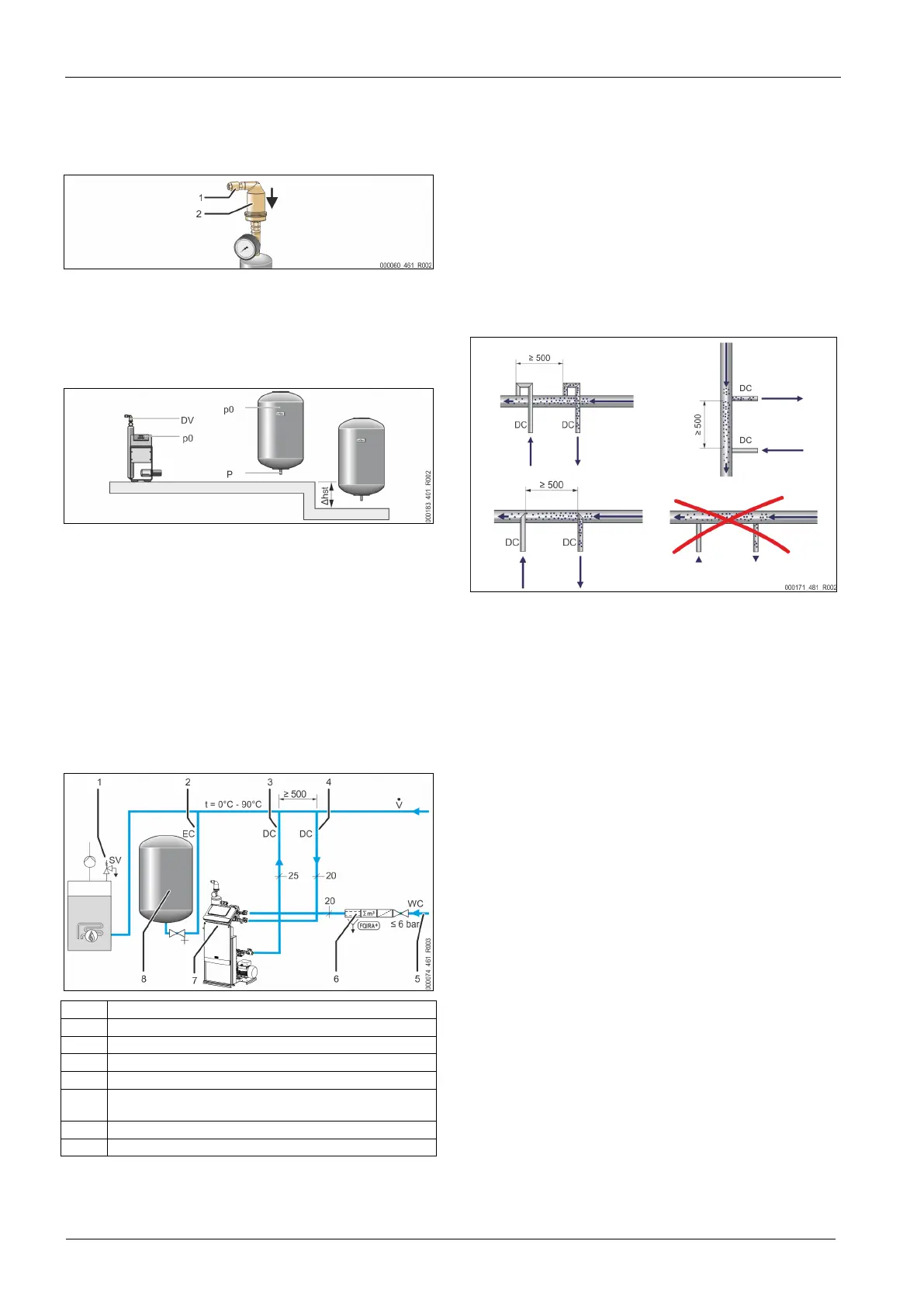
6.3.1 Fitting the add-on components
Install the "DV" degassing valve (2) with the check valve (1) on the "VT" vacuum
spray tube. Check all screw fittings of the Servitec for proper seating.
6.3.2 Installation location
The Servitec is installed on the floor. Select the attachment means according to
the floor properties and the weight of the Servitec.
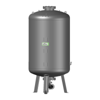
Note!
Consider a potential difference in head "h
st
" between the expansion
vessel and the device when calculating the "P
0
" minimum operating
6.3.3 Hydraulic connection
6.3.3.1 Degassing line to the system
The device requires two "DC" degassing lines to the system. One degassing line is
intended for gas-rich water from the system, and the other one serves to return
the degassed water to the system. Shut-off devices for both degassing lines have
been pre-installed at the device. The connections of the degassing lines must be
made within the main flow volume of the facility system.
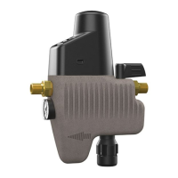
Device installation in a heating system – Pressure maintenance with expansion
vessel
1 "SV" safety valve
2 "EC" expansion line
3 "DC" degassing line (degassed water)
4 "DC" degassing lines (gas-rich water)
5 "WC" make-up line
6
Optional equipment and accessories see chapter 4.6 "Optional
equipment and accessories" on page 6 .
7 Servitec
8 Expansion vessel
The degassing lines into the system are to be installed near the connection point
of the "EC" expansion line. This ensures stable pressure conditions.
If you operate the device with pressure-dependent water make-up, you must
install the system near the diaphragm-type expansion vessel. This ensures that
the pressure in the diaphragm-type expansion vessel is monitored. In this case,
select the "Magcontrol" operating mode in the controller.
Note!
Ensure the integration in the "V" main flow volume when using
switching variants with hydraulic switching points and return
admixtures.
For switching and make-up variants, see chapter 6.4 "Switching
and make-up variants" on page 9 .
Installation detail of the "DC" degassing line
Connect the "DC" degassing lines as shown below.
• Ensure that particulate dirt cannot enter and thus create an overload of the
Servitec's "ST" dirt trap.
• Connect the degassing line for gas-rich water upstream of the degassing
line for degassed water in system direction of flow.
• The water temperature must be in the range > 0 °C – 90 °C. The return line
side should be preferred for heating systems. This ensures the permissible
temperature range for degassing.