— English Servitec 35-95 with
— 18.12.2019 - Rev. A
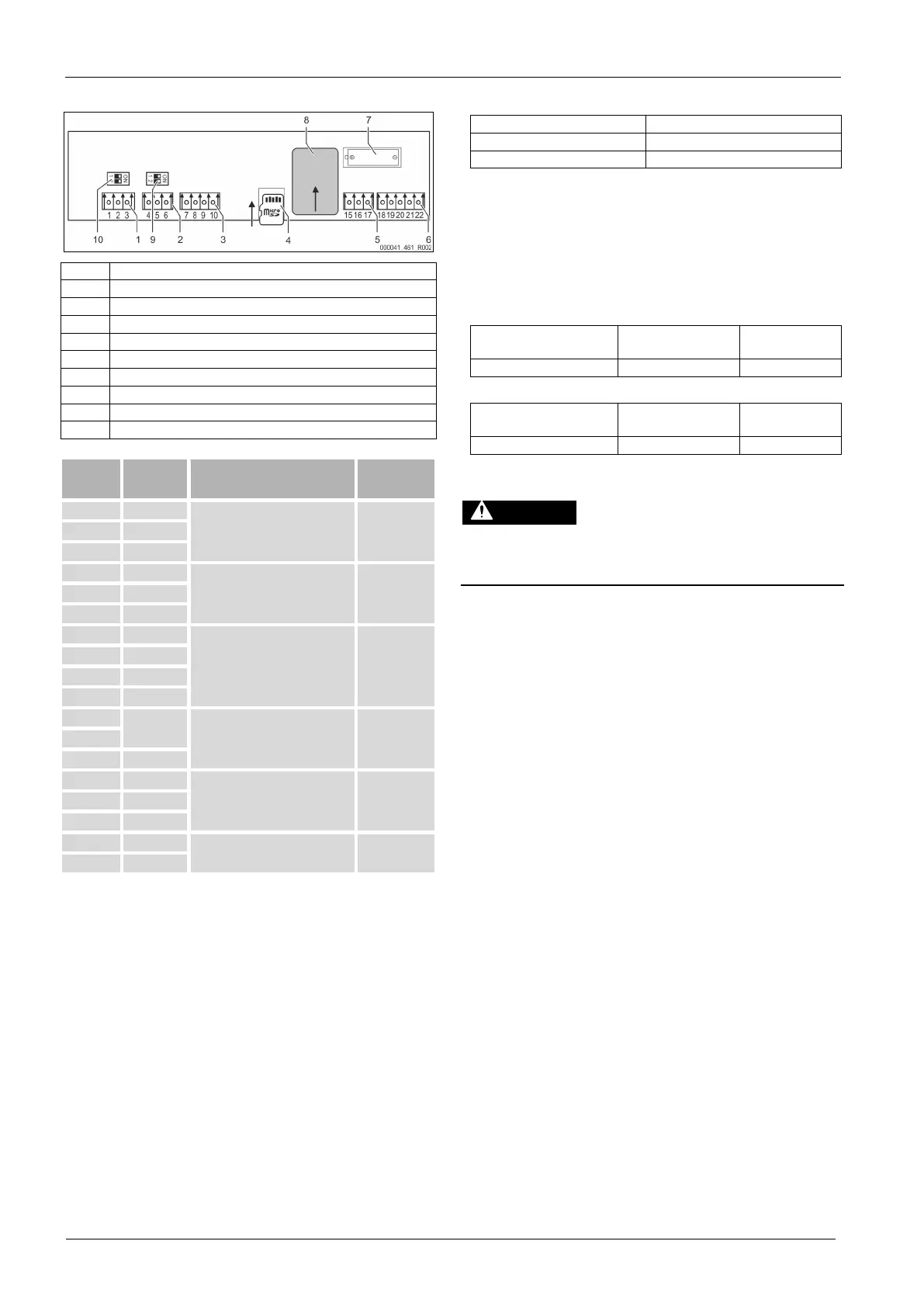
6.5.2 Terminal plan, operating unit
1 RS -485 networking
2 RS -485 module
3 I/O interface
4 SD card
5 10 V supply
6 Analogue outputs for pressure and conductivity
7 Battery compartment
8 Anybus module slot
9 Terminators RS-485 (dip switch)
10 Terminators RS-485 (dip switch)
1 A
RS-485 interface.
S1 networking.
--- 2 B
3 GND S1
4 A
RS-485 interface.
S2 modules: Extension or
communication module.
User supplied 5 B
6 GND S2
7 +5 V
I/O interface: Interface to the main
board
Factory
8 R × D
9 T × D
10 GND IO1
15
10 V~
10 V supply. Factory 16
17 FE
18 PE (shield)
Analogue output: Pressure.
Standard 4 – 20 mA.
(Optional 2 – 10 V)
User supplied 19 Pressure
20 GNDA
21 LF
Analogue output conductivity Lf. User supplied
22 GNDB
6.5.3 RS-485 interface
Use the S2 RS-485 interface to retrieve all controller data and to enable the
communication with control centres or other devices.
– S2 interface
• "PIS" pressure.
• Operating modes of the "PU" pump.
• Values of the "FQIRA +" contact water meter.
• All messages, see chapter 9.2 "Messages" on page 20 .
• All entries in the fault memory.
The following accessories are available for interface communication.
– Bus modules
• Profibus-DP.
• Ethernet.
• Optional I/O module.
• Modbus RTU.
6.6 Installation and commissioning certificate
Data shown on the type plate: P
0
Type: P
SV
Manufacturing number:
This device has been installed and commissioned in accordance with the
instructions provided in the operating manual. The settings in the controller
match the local conditions.
-set values of the device are changed, you must enter
this information in the Maintenance certificate, see chapter
10.4
"Maintenance certificate " on page 23 .
For the installation
Place, date Company Signature
For the commissioning
Place, date Company Signature
7 Commissioning
Risk of burns on hot surfaces
Hot surfaces in heating systems can cause burns to the skin.
• Wear protective gloves.
• Please place appropriate warning signs in the vicinity of the device.
installation and start-up have been carried out correctly
using the installation, start
-up and maintenance certificate. This action
is a prerequisite for the making of warranty claims.
Have the Reflex Customer Service carry out commissioning and
7.1 Checking the requirements for commissioning
The Servitec will be ready for initial commissioning when the tasks described in
the "Installation" chapter have been completed.
• The Servitec has been mounted.
• The connections of the Servitec to the system have been created and plant
system pressure maintenance is operational.
– Degassing line to the facility system.
– Degassing line from the facility system.
• The water-side connection of the Servitec to the make-up has been created
and is operational, if automatic make-up is required.
• The connection pipes of the Servitec have been purged and cleaned of
welding residue and dirt before commissioning.
• The entire facility system is filled with water and all gases have been
vented in order to ensure a circulation through the entire system.
• The electrical connection has been created according to applicable
national and local regulations.