Servitec 35-95 with
— 18.12.2019 - Rev. A
English —
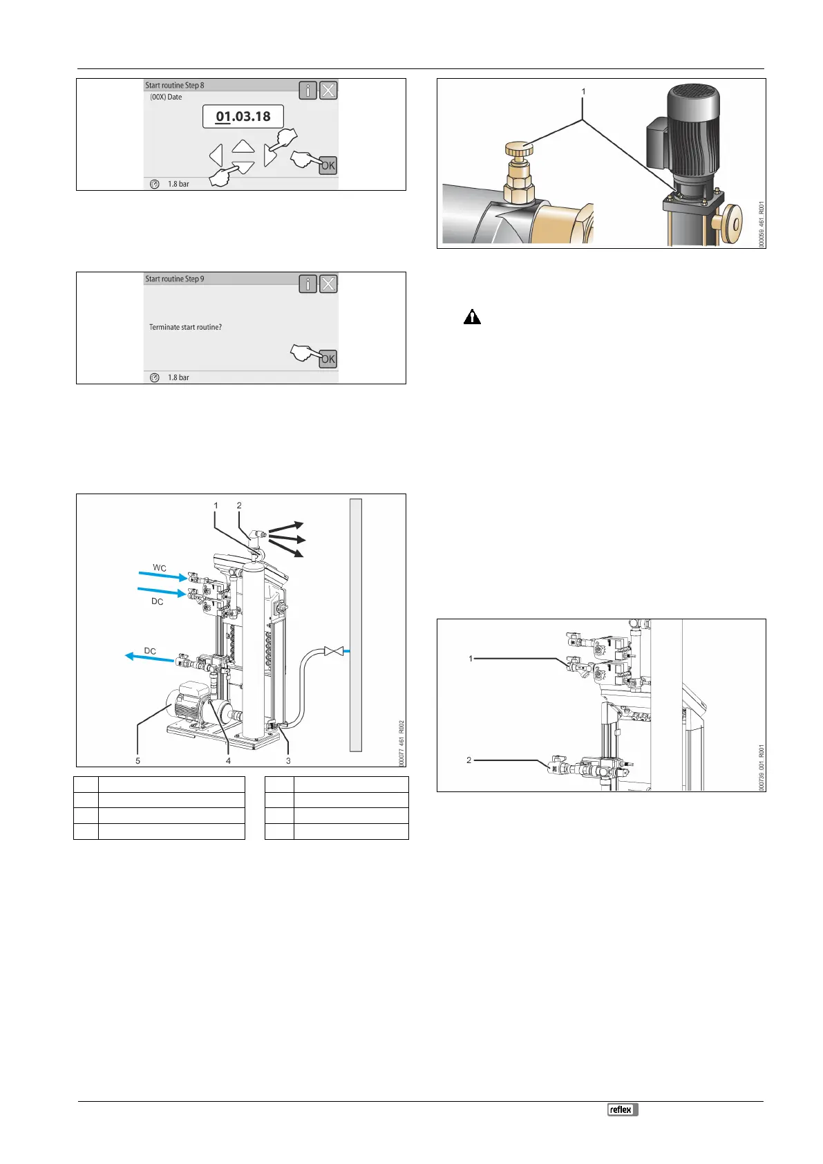
8. Set the date. The date of an alarm will be stored in the controller's fault
memory.
– Use the "Left" and "Right" buttons to select the display value.
– Use the "Up" and "Down" buttons to change the display value.
– Confirm your entries with "OK".
9. Press "OK" to conclude the start routine.
Note!
After successful conclusion of the start routine, you are in Stop mode. Do
not yet switch to Automatic mode.
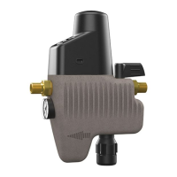
7.4 Filling the device with water and venting
1 Vacuum gauge "PI" 5 Pump "PU"
2 Degassing valve "DV" WC Make-up pipe
3 Feed and drain cock "FD" DC Degassing lines
4 "AV" venting screw
1. Use the facility system to fill the Servitec.
– After you have opened the "DC" ball valves, the vacuum spray tube
will autonomously fill if the facility system provides sufficient water.
2. Optional
– Use the feed and drain cock (3) to fill water into the Servitec.
– Connect a hose at the feed and drain cock (3) of the "VT" vacuum
spray pipe.
3. Fill the vacuum spray pipe with water.
– Air escapes via the degassing valve (2) and the water pressure can be
read at the vacuum gauge (1).
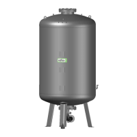
Vent the pump:
4. Turn the venting screw (1) until air or a water/air mixture escapes.
5. If required, use a screwdriver to rotate the pump at the fan wheel of the
pump motor.
CAUTION – Risk of injury due to pump start-up! Hand injury due to a
pump start-up. Switch the pump to a zero-volts state before turning the
pump motor at the fan wheel with a screwdriver.
CAUTION – Device damage. Pump damage due to a pump start-up. Switch
the pump to a zero-volts state before turning the pump motor at the fan
wheel with a screwdriver.
– Water/air mixtures are removed from the pump.
6. Re-tighten the venting screw when only water escapes.
7. Close the feed and drain cock.
Filling and venting is concluded.
Note!
The "PU" pump must not be switched on when the Servitec is filled with
water.
Note!
Do not fully unscrew the
venting screw. Wait until air-free water
appears. Repeat the venting process until the "PU" pump is fully vented.
7.5 Vacuum test
Perform the vacuum test to ensure the proper functioning of the device.
1 Close the ball valve (1) with the dirt trap of the "DC" feed line to the spray
pipe. The second ball valve (2) in the feed line from the "DC" pump to the
system remains open.
2 Generate a vacuum in manual mode of the controller.
• Switch to Manual mode.
– For information about controller operation, see chapter 7.4
"Operator panel" on page 13 .
– For more information about Manual mode, see chapter 8.1.2
"Manual mode" on page 17 .
3 Use "Circulate" to activate continuous degassing until the vacuum gauge
indicates a stable vacuum.
• Note the vacuum indicated on the vacuum gauge.