Servitec 35-95 with
— 18.12.2019 - Rev. A
English —
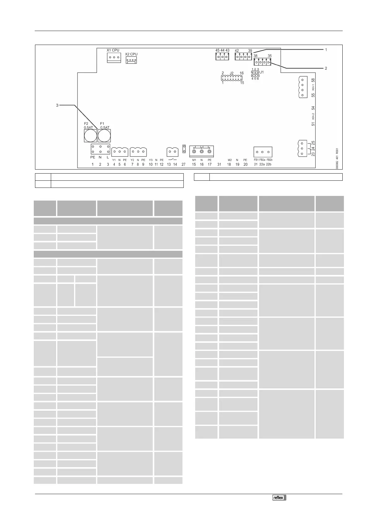
6.5.1 Terminal plan, connection component
1 Pressure 3 Fuses
2 Conductivity
Supply
X0/1 L
Supply 230 V, maximum
16 A.
• Servitec 35-95
User supplied X0/2 N
X0/3 PE
Circuit board
13 NO
Dry-running protection
message (floating).
User, optional
14 COM
22a FB2a COM External make-up request.
– With Levelcontrol
setting.
Input 230 V signal via
L+N.
User, optional
22b FB2b NO
23 NC
Group message (floating). User, optional 24 COM
25 NO
43 +24 V
• E1, digital input from
the contact water
meter.
Terminal 43+44.
E1, user
option
E2, factory
44 E1
• E2, insufficient water
switch.
Terminal 43+45.
45 E2
1 PE
Voltage supply. Factory 2 N
3 L
4 Y1
WV make-up valve Pre-wired 5 N
6 PE
7 Y2
CD degassing control valve Pre-wired 8 N
9 PE
10 Y3
--- --- 11 N
12 PE
15 M1 "PU" pump Pre-wired
16 N
17 PE
18 M2
--- --- 19 N
20 PE
21 FB1 Voltage monitoring PU
pump
Pre-wired
27 M1 PU pump supply Pre-wired
31 M2 --- ---
35 +18V
Analogue input conductivity
Lf.
User, optional
36 GND
37 AE
38 Shielding
39 + 18 V (blue)
Analogue input "PIS"
pressure measuring.
– For pressure indication
and make-up with the
"Magcontrol" setting.
Pre-wired
40 GND
41 AE (brown)
42 Shielding (black)
51 GND
--- ---
52 +24 V (supply)
53 0–10V (correcting
variable)
54 0–10V (feedback)
55 GND (black)
Control ball valve"PV"
– For regulating the
hydraulic adjustment
of degassing.
Pre-wired
56
+24 V (supply)
(red)
57
0–10V (correcting
variable) (white)
58
0–10V (feedback)
(orange)