Variomat Touch — 09.2020 - Rev. A
7.5.4 RS-485 interface
Use the S1 and S2 RS-485 interfaces to retrieve all controller data and to enable
the communication with control centres or other devices.
• S1 interface
– A maximum 10 devices can be used in a master-slave linked circuit
via the this interface.
• S2 interface
– "PIS" pressure and "LIS" level.
– Operating modes of the "PU" pumps.
– Operating states of the motorised ball valve/solenoid valve.
– Values of the "FQIRA +" contact water meter.
– All messages.
– All entries in the fault memory.
The following bus modules form part of the optional accessories available for
interface communication.
Note!
If required, please contact the Reflex Customer Service for the protocol
of the RS-485 interface, details of the connections and information about
the accessories offered.
7.5.4.1 Connecting the RS-485 interface
Main circuit board of the Control Touch controller.
Connection terminals for RS-485 connection
Proceed as follows:
1. Use a screened cable to connect the RS-485 interface to the main circuit
board.
• S 1
– Terminal 1 (A+)
– Terminal 2(B-)
– Terminal 3(GND)
2. Connect the cable screen at one side.
• Terminal 18
3. Activate the terminator on the main circuit board.
• Dip switch 1
7.6 Installation and commissioning certificate
Note!
The installation and commissioning certificate can be found at the end
of the operating manual.
Note!
Confirm that installation and start-up have been carried out correctly
using the installation and commissioning certificate. This action is a
prerequisite for the making of warranty claims.
– Have the Reflex Customer Service carry out commissioning and
the annual maintenance.
8.1 Checking the requirements for commissioning
The device will be ready for commissioning when the tasks described in the
"Installation" chapter have been completed. The system designer or an assigned
expert is responsible for carrying out the commissioning. Commission the
storage tank according to the information in the corresponding installation
manual. Note the following information on commissioning:
• The control unit is connected to the primary tank and the secondary tanks,
if provided.
• The water connections of the tanks to the facility system are established.
• The tanks are not filled with water.
• The valves for emptying the tanks are open.
• The facility system is filled with water and gas-vented.
• The electrical connection has been created according to applicable
national and local regulations.
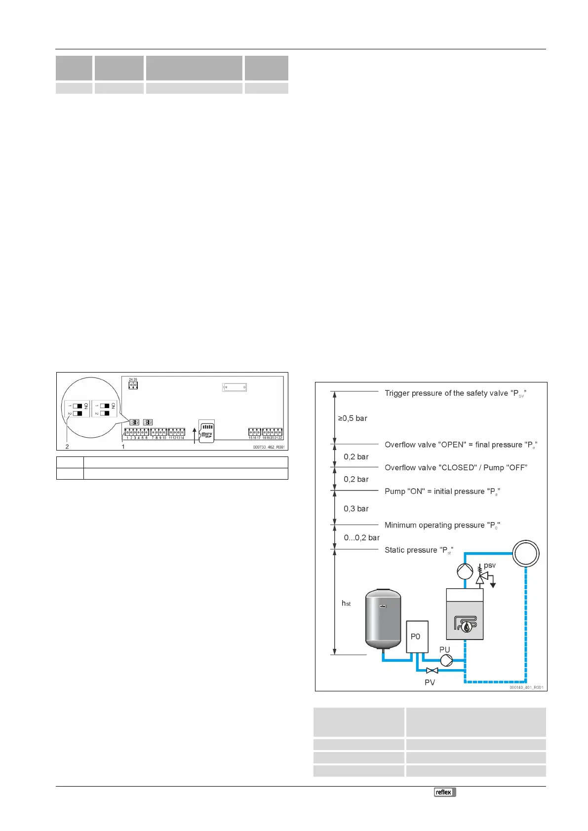
8.2 Variomat switching points
The "P
0
" minimum operating pressure is determined by the location of the
pressurisation. The controller calculates the switching points for the solenoid
valve "PV" and the pump "PU” from the "P
0
" minimum operating pressure.
The "P
0
" minimum operating pressure is calculated as follows:
Enter the calculated value in the start routine
of the controller, see chapter 8.3 "Modifying
the controller's start routine" on page 16 .
for safety temperatures ≤ 100 °C
for safety temperatures = 110 °C