Variomat Touch — 09.2020 - Rev. A
Note!
Arrange for maintenance tasks must be carried out only by specialist
personnel or Reflex Customer Service.
11.1 Maintenance schedule
The maintenance schedule is a summary of maintenance tasks to be carried out
regularly.
Check for leaks.
• "PU" pump.
• Screw connections.
• Check valve downstream of "PU"
pump.
Clean "ST" dirt trap.
– see chapter 11.1.1 "Cleaning the dirt
trap" on page 24 .
Depending on the
operating conditions
Clear sludge from the primary tank and the
secondary tanks.
– see chapter 11.1.2 "Cleaning the
tanks" on page 24 .
Depending on the
operating conditions
Check the make-up switching points.
– see chapter 11.2 "Checking switching
points" on page 24 .
Check the Automatic mode switching
points.
– see chapter 11.2 "Checking switching
points" on page 24 .
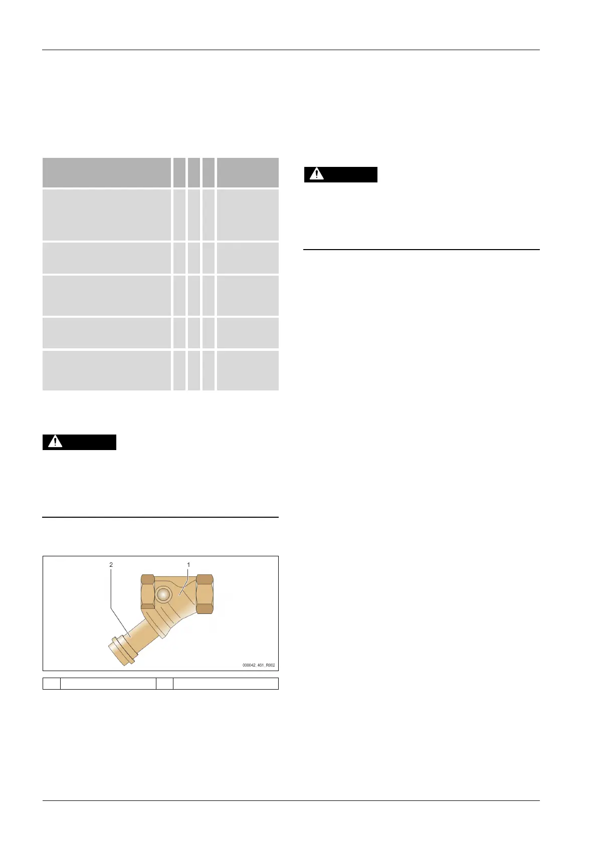
11.1.1 Cleaning the dirt trap
Risk of injury due to pressurised liquid
If installation, removal or maintenance work is not carried out correctly, there
is a risk of burns and other injuries at the connection points, if pressurised
hot water or hot steam suddenly escapes.
• Ensure proper installation, removal or maintenance work.
• Ensure that the system is de-pressurised before performing installation,
removal or maintenance work at the connection points.
The "ST" dirt trap must be cleaned after the expiry of the continuous degassing
time at the latest. An inspection is also required after longer lasting operation.
1. Switch to Stop mode.
2. Close the ball vales upstream of the "ST" dirt trap (1) and the primary
vessel.
3. Slowly unscrew the dirt trap insert (2) from the dirt trap in order for the
residual pressure to escape from the pipeline segment.
4. Pull the mesh from the dirt trap insert and rinse it with clear water. Use a
soft brush for cleaning.
5. Re-insert the mesh into the dirt trap insert, check the gasket for damage,
and screw the dirt trap insert back into the housing of the "ST" (1) dirt trap.
6. Open the ball valve upstream of the "ST" dirt trap (1) and ball valve to the
primary vessel.
7. Vent the "PU“ pump, see chapter 8.5 "Venting the pump" on page 17 .
8. Switch to Automatic mode.
Note!
Clean all other installed dirt traps (in the Fillset, for example).
11.1.2 Cleaning the tanks
Risk of injury due to pressurised liquid
If installation, removal or maintenance work is not carried out correctly, there
is a risk of burns and other injuries at the connection points, if pressurised
hot water or hot steam suddenly escapes.
• Ensure proper installation, removal or maintenance work.
• Ensure that the system is de-pressurised before performing installation,
removal or maintenance work at the connection points.
Clean the primary tank and the secondary tanks from sludge deposits.
1. Switch to Stop mode.
2. Empty the tanks.
– Open the "FD" feed and drain cocks and empty the tanks completely
from water.
3. Remove the hose connection between the primary tank and the device and
the secondary tank, if provided.
4. Remove the lower vessel covers from the tanks.
5. Remove any sludge from the covers and the spaces between the
diaphragms and the tanks.
• Check the diaphragms for tearing.
• Check the tank interior walls for corrosion.
6. Reinstall the covers on the tanks.
7. Reinstall the flange connection betweens the primary tank and the device
and the secondary tank, if provided.
8. Close the "FD" feed and drain cocks at the tanks.
9. Use the "FD" feed and drain cock to fill the primary tank with water, see
chapter 8.4 "Filling the tanks with water" on page 17 .
10. Switch to Automatic mode.
11.2 Checking switching points
Prerequisite for checking the switching points are the following correct settings:
• Minimum operating pressure P
0
, see chapter 8.2 "Variomat switching
points" on page 15 .
• Level sensor at the primary tank.
Preparation
1. Switch to Automatic mode.
2. Close the cap valves upstream of the tanks and the "EC" expansion lines.
3. Record the displayed filling level (value in %).
4. Drain the water from the tanks.
Checking the cut-in pressure
5. Check the cut-in and cut-out pressure of the "PU" pump.
– The pump cuts in at P
0
+ 0.3 bar.
– The pump cuts out at P
0
+ 0.5 bar.
Checking the Make-up "On"
6. If necessary, check the make-up value displayed at the controller.
– The automatic make-up is activated at a level display of 20 %.
Checking Insufficient water "On"
7. Switch off the make-up and continue to drain water from the tanks.
8. Check the displayed value for the "Insufficient water" filling level message.
– Insufficient water "On" is displayed at the controller at a minimum
filling level of 5 %.
9. Switch to Stop mode.
10. Switch off the main switch.
Cleaning the tanks
If necessary, remove condensate from the tanks, see chapter 11.1.2 "Cleaning
the tanks" on page 24 .
Activating the device