Variomat Touch — 09.2020 - Rev. A
Risk of burns on hot surfaces
Hot surfaces in heating systems can cause burns to the skin.
• Wear protective gloves.
• Please place appropriate warning signs in the vicinity of the device.
Risk of injury due to falls or bumps
Bruising from falls or bumps on system components during installation.
• Wear personal protective equipment (helmet, protective clothing,
gloves, safety boots).
Note!
Confirm that installation and start-up have been carried out correctly
using the installation, start-up and maintenance certificate. This action is
a prerequisite for the making of warranty claims.
– Have the Reflex Customer Service carry out commissioning and
the annual maintenance.
7.1 Installation conditions
7.1.1 Incoming inspection
Prior to shipping, this device was carefully inspected and packed. Damages
during transport cannot be excluded.
Proceed as follows:
1. Upon receipt of the goods, check the shipment for
• completeness and
• possible transport damage.
2. Document any damage.
3. Contact the forwarding agent to register your complaint.
7.2 Preparatory work
Condition of the delivered device:
• Check all screw connections of the device for tight seating. Tighten the
screws as necessary.
Preparing the device installation:
• No access by unauthorised personnel.
• Frost-free, well-ventilated room.
– Room temperature 0 °C to 45 °C (32 °F to 113 °F).
• Level, stable flooring.
– Ensure sufficient bearing strength of the flooring before filling the
tanks.
– Ensure that the control unit and the tanks are installed on the same
level.
• Filling and dewatering option.
– Provide a DN 15 filling connection according to DIN 1988 - 100 and
En 1717.
– Provide an optional cold water inlet.
– Prepare a drain for the drain water.
• Electric connection, see chapter 6 "Technical data" on page 8 .
• Use only approved transport and lifting equipment.
– The load fastening points at the tanks must be used only as
installation resources.
7.3 Execution
Damage due to improper installation
Additional device stresses may arise due to the connection of pipes or
system equipment.
• Ensure that pipes are connected from the device to the system without
them being stressed or strained.
• If necessary, provide support structures for the pipes or equipment.
For installation, proceed as follows:
• Position the device.
• Complete the primary tank and the optional secondary tanks.
• Create the water-side connections of the control unit to the system.
• Create the interfaces according to the terminal plan.
• Install the water connections between optional secondary tanks to each
other and to the primary tank.
Notice!
For installation, note the operability of the valves and the inlet options of
the connecting lines.
Determine the positions for the control unit, primary vessels and secondary
vessels (if used).
• Variomat 2-1:
– The control unit can be installed on either side or in front of the
primary vessel. The distance of the control unit to the primary vessel
results from the connection set supplied.
• Variomat 2-2:
– The control unit can be installed on either side or in front of the
primary vessel. The distance of the control unit to the primary vessel
results from the connection set supplied.
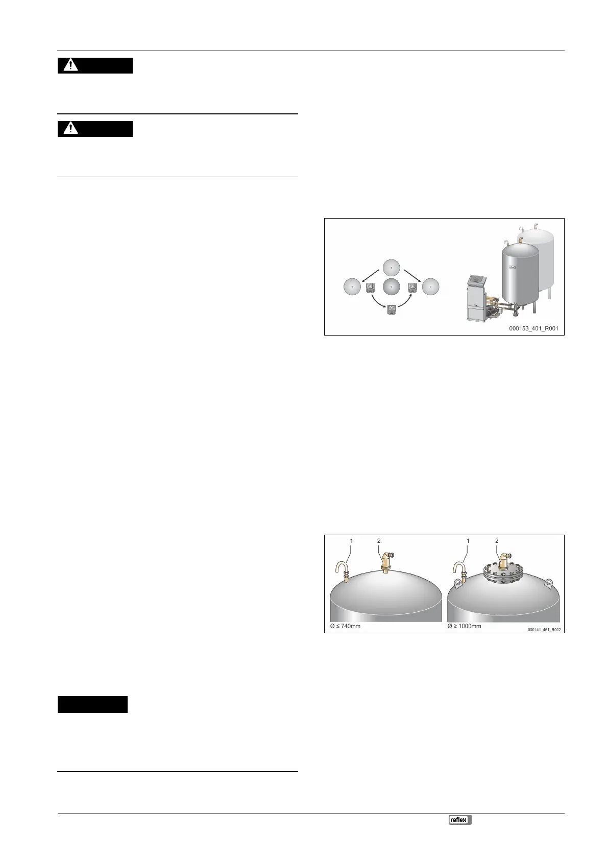
7.3.2 Installation of add-on components for the tanks
The add-on components are packed in plastic bags and attached to the base of
the vessels.
• Pressure compensation elbow (1).
• Reflex Exvoid with pre-fitted check valve (2)
• "LIS" pressure pick-up
For add-on components, proceed as follows:
1. Install the Reflex Exvoid (2) at the connection of the corresponding vessel.
2. Remove the protective cap from the degassing valve.
3. Use the compression fitting to install the pressure compensation elbow (1)
for ventilation at the vessels.
Note!
Install the "LIS" pressure pick-up only after finalising the installation of
the primary vessel, see chapter 7.3.3 "Tank installation" on page 10 .
Note!
To ensure fault-free operation, do not seal off the aeration and
ventilation.