I/O module (optional expansion module)
Variomat Touch — 09.2020 - Rev. A
Permissible operating temperature:
Permissible storage temperature:
230 V AC, 50 – 60 Hz (IEC 38)
• 6 floating relay outputs (changeover)
• 3 digital inputs 230 V AC
• 3 digital inputs 24 V AC
• 2 Analogue outputs (these are not required, because they are already
contained in the Control Touch controller).
Interfaces to the controller
• RS-485
• 19.2 kbit/s
• Floating
• connection with plug or screw terminals
• RSI-specific protocol
Danger to life from electric shock!
Risk of serious injury or death due to electric shock. Some parts of the main
board may still carry 230 V voltage even with the device physically isolated
from the 230 V power supply.
• Before you remove the covers, completely isolate the device controller
from the power supply.
• Verify that the main circuit board is voltage-free.
5.2.1 Terminator settings in RS-485 networks
Examples for the activation and deactivation of terminators in RS–485 networks.
• DIP switches 1 and 2 are located on the main board of the controller.
• Maximum length for an RS–485 connection is 1000 metres
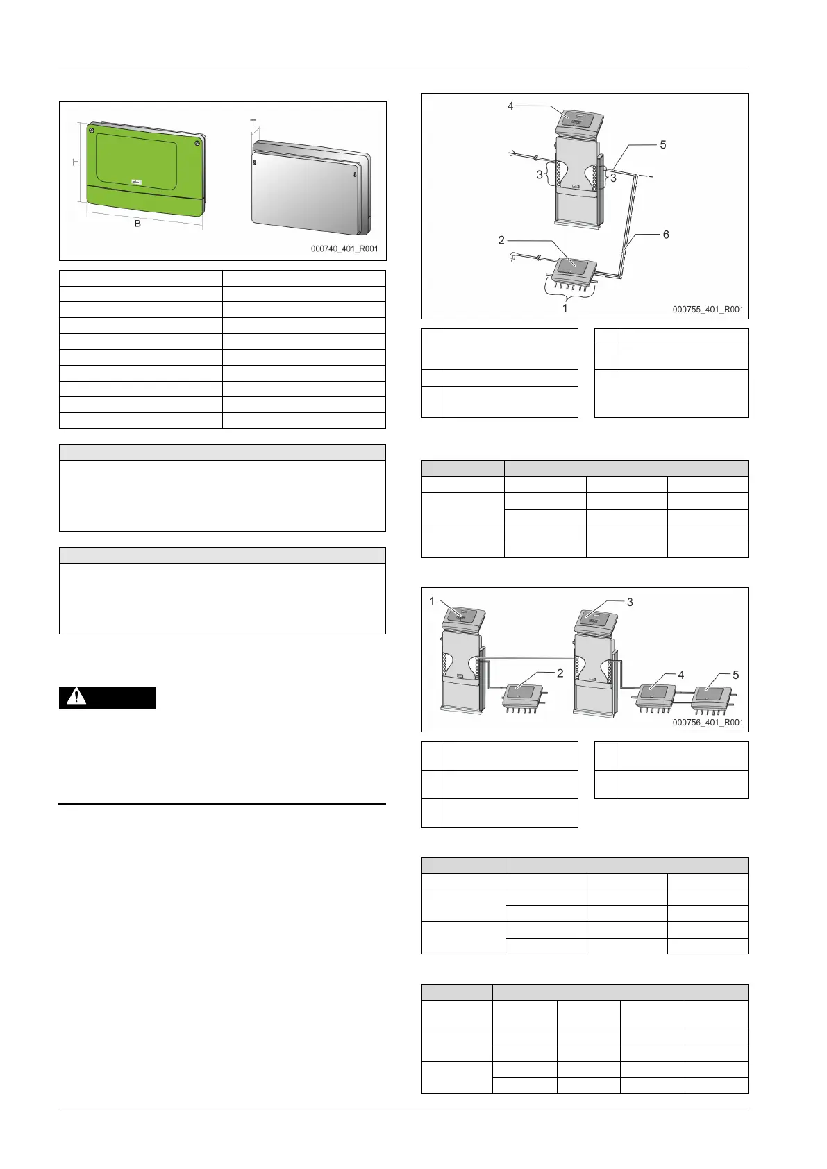
Device controller with I/O module
Relay outputs of the I/O
module*
• 6 digital outputs
"Control Touch" controller
Optional RS-485 connection
• Master - Slave
• Field bus
Connections of the I/ O
conductors
* The 2 analogue outputs are not required because the Control Touch controller
already has two analogue outputs for pressure and level measurement.
Device controllers and I/O module in Master-Slave function
Control Touch controller in
Master function
I/O module for the Slave
function
I/O module for the Master
function
Control Touch controller in
Slave function