Variomat Touch — 09.2020 - Rev. A
Risk of electric shock!
Risk of serious injury or death due to electric shock. Some parts of the main
board may still carry 230 V voltage even with the device physically isolated
from the 230 V power supply.
• Before you remove the covers, completely isolate the device controller
from the power supply.
• Verify that the main circuit board is voltage-free.
Fusing is provided on the I/O module's main circuit board.
Microfuse F1 (250 V, 0, 16 A slow)
Proceed as follows:
1. Disconnect the I/O module from the power supply.
• Pull the power plug from the bus module.
2. Open the terminal space cover.
3. Remove the housing cover.
4. Replace the defective fuse.
5. Re-attach the housing cover.
6. Close the terminal space cover.
7. Reconnect the power supply for the module.
The fuse replacement is completed.
6 Technical data
6.1 Control unit
Note!
The following values apply for all control units:
– Permissible flow temperature:
– Permissible operating temperature:
– Permissible ambient temperature:
– Degree of protection:
– Number of RS-485 interfaces:
– IO module:
– Electrical voltage control unit:
– Noise level:
120 °C
70 °C
0 °C – 45 °C
IP 54
1
Optional
230 V; 2 A
55 db
Electrical connection
[Hz; A]
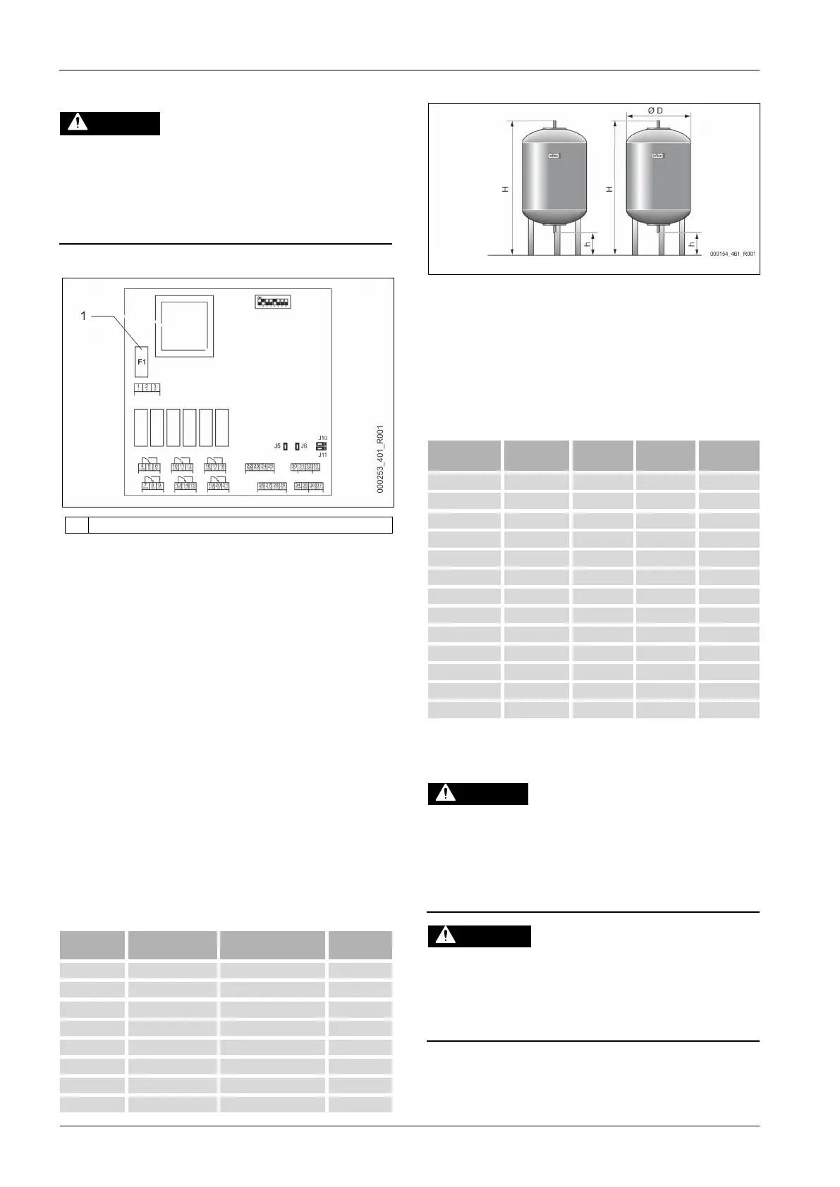
Note!
Optional heat insulation is available for primary tanks, see chapter 4.6
"Optional equipment and accessories" on page 5 .
Note!
The following values apply for all vessels:
– Operating pressure:
– Connection:
Risk of serious injury or death due to electric shock.
If live parts are touched, there is risk of life-threatening injuries.
• Ensure that the system is voltage-free before installing the device.
• Ensure that the system is secured and cannot be reactivated by other
persons.
• Ensure that installation work for the electric connection of the device is
carried out by an electrician, and in compliance with electrical
engineering regulations.
Risk of injury due to pressurised liquid
If installation, removal or maintenance work is not carried out correctly, there
is a risk of burns and other injuries at the connection points, if pressurised
hot water or hot steam suddenly escapes.
• Ensure proper installation, removal or maintenance work.
• Ensure that the system is de-pressurised before performing installation,
removal or maintenance work at the connection points.