I/O module (optional expansion module)
Variomat Touch — 09.2020 - Rev. A
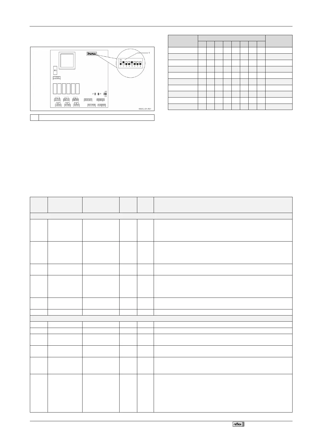
5.2.2 Setting the module address
Setting of the module address on the I/O module's main circuit board
• For setting the module address
• Variable setting to ON or OFF
• Permanently to position ON
• For internal testing
• To position OFF during operation
Use DIP switches 1 – 4 to set the module address.
Proceed as follows:
1. Pull out the mains plug of the I/O module.
2. Open the housing cover.
3. Set DIP switches 1 – 4 to position ON or OFF.
5.2.3 I/O module default settings
The inputs and outputs of the I/O module each have default settings.
These default settings can be changed, if required, and adjusted to local
conditions.
Responses by the inputs 1 – 6 of the I/O module are recorded and displayed in
the device controller's fault memory.
Note!
• Default settings apply to software version V1.10 and higher.
• All digital inputs and outputs can be set freely as option. The
setting is carried out by Reflex Customer Service, see
chapter 13.1 "Reflex Customer Service" on page 26
Signal on the input triggers the following action
External temperature
monitoring
• Solenoid valves are closed.
• Solenoid valve (2) in overflow line (1)
• Solenoid valve (3) in overflow line (2)
• Output relay (1) is switched.
External signal,
Minimum pressure
• Solenoid valves are closed.
• Solenoid valve (2) in overflow line (1)
• Solenoid valve (3) in overflow line (2)
• Output relay (2) is switched.
• Solenoid valve (1) in make-up line is manually opened.
• Output relay (5) is switched.
• Pumps (1) and (2) are switched off.
• Solenoid valves (2) and (3) in the overflow lines are closed.
• Solenoid valve (1) in the make-up line is closed.
• Switches "Group alarm" in the device controller.
• Pump (1) is manually switched on.
• Output relay (5) is switched.
Solenoid valve (1) is opened.
• Below minimum pressure.
• "ER 01" message in the controller
• Maximum pressure exceeded
• "ER 10" message in the controller
Switches in manual mode
Switches in stop mode
Switches with inputs 3,5,6 active
• Make-up setting values exceeded.
• Switches the following messages in the device controller:
• "ER 06", Make-up time
• "ER 07", Make-up cycles
• "ER 11", Make-up quantity
• "ER 15", Make-up valve
• "ER 20", Maximum make-up quantity