Regency
®
P33-4 Zero Clearance Direct Vent Gas Fireplace
45
INSTALLATION
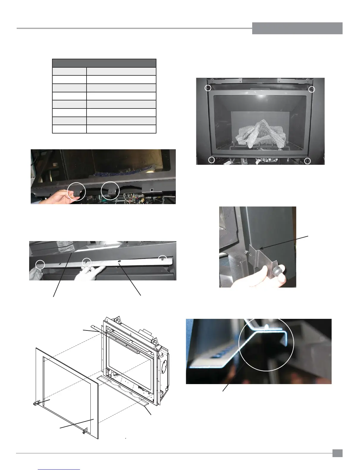
1) Install the control shield with 2 #8 - 1/2" Phillips screws to the bottom
of the fl ush door as shown in Diagram 1.
3) Loosen 4 phillips head screws located inside fi rebox, for screw locations
see Diagram 4. Install mounting frame and retighten screws.
4) After the frame has been installed, locate the 2 phillips head screws
on lower part of the mounting frame- see Diagram 3 for location.
Slide on the 2 faceplate supports and retighten the screws.
5) The top of the faceplate has a fl ange that hooks over the top of the
fl ush door.
2) Install the heat defl ector on the fi re box as shown in Diagrams 2 &
3.
Loosen 3 Phillips head screws already in fi rebox, slide heat defl ector
on to screws and retighten.
Diagram 1
Diagram 2
Top of Unit
Heat Defl ector
Diagram 3
Diagram 4
Diagram 5
Bend
Diagram 6
Flange
Mounting Frame
Heat Defl ector
Control Shield
Faceplate Support
Faceplate
434-033 Mounting Plate
434-514 Faceplate Support
434-032 Control Shield
434-018F Heat Defl ector
434-516 Faceplate - Black
434-516BL Faceplate - Blue
434-516R Faceplate - Red
434-517 Faceplate - Stainless Steel
Important: Positon of bracket must be as shown in Diagram 5, with
bend away from fi replace.
CONTEMPORARY FACEPLATE INSTALLATION PART 3