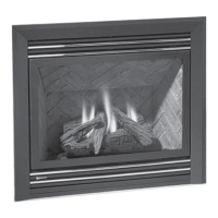
P36-10 Zero Clearance Direct Vent Gas Fireplace | 13
|
13
installation
Install Side Nailing Strips, Top Facing
Support, and Top Standoffs before unit is
slipped into position. See the "Unit As-
sembly Prior to Installation" section for
assembly details.
1) Determine the total thickness of facing mate-
rial (e.g. non combustible plus ceramic tiles)
to allow the finished surface to be flush with
the front of the unit. Total facing thickness can
vary from 1/2" (13mm) to 1-1/4" (32mm) thick.
Add a second steel stud at midpoint for ease
of installation/securing the non combustible
board. See Diagram 5.
FRAMING AND FINISHING
2) Frame in the enclosure for the unit with
framing material. The framed opening is
40-3/4" high x 36-1/4" wide x 12-3/4" deep
(1036mm high x 921mm wide x 324mm
deep).
Note: Header must be installed vertically. If
Header is installed horizontally, it must be
steel.
3) For exterior walls, insulate the enclosure
to the same degree as the rest of the
house, apply vapour barrier and drywall,
as per local installation codes. (Do not
insulate the fireplace itself.)
4) The top of the unit must not be closer
than 32" (813mm) to the ceiling.
Note: 40-1/2" (1029mm) is the minimum
height for both ex termination or
rigid pipe venting.
All other framing may be of combustible
materials, i.e. 2 x 4, 2 x 6
Note: The unit does not have to be
completely enclosed in a chase. The
clearance on top of the unit is 0" to
the standoffs so combustible building
materials can be laid directly on top
of the standoffs. You must maintain
1-1/2" (38mm) clearance from the
vent to combustible materials for ex
(1-1/4" for Rigid Pipe).
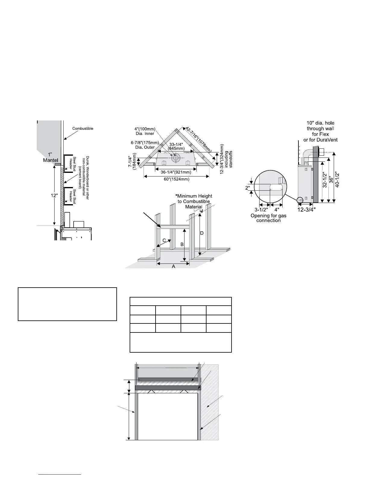
5) Use steel studs for framing where the
1-1/2" (38mm) clearance from the vent to
combustible material cannot be maintained,
e.g. front top header.
Note: Secure the 12" x 36" non-combustible board
supplied with this unit is directly above the unit as
shown. Install a steel stud directly above the unit
as shown to secure the non -combustible material.
30-1/2"
(775mm)
36"
(914mm)
Non-combustible
Material (supplied)
Steel stud on edge
2nd Steel stud on edge
(install after unit in place)
12"
(305mm)
Wood stud
Wood stud
Drywall
Framing Dimensions
A B C D
36-1/4" 40-3/4" 12-3/4" 46"*
921mm 1036mm 324mm 1168mm*
* 'D' is Minimum height to combustible materials
including the Minimum 2" (51mm) Top clearance
to the Horizontal Vent.
Diagram 1
Diagram 2
Diagram 3
Diagram 4
Diagram 6
Diagram 5
Steel stud on
edge