34 | P36-10 Zero Clearance Direct Vent Gas Fireplace
|
34
installation
CONVERSION FROM NG TO LP
FOR P36-10 USING SIT 829 NOVA GAS VALVE
1
10.30.14
919-472
Conversion from NG to LPG for
P36D-10 / P36-10
THIS CONVERSION MUST BE DONE BY A QUALIFIED GAS FITTER
IF IN DOUBT DO NOT DO THIS CONVERSION !!
1. Shut off the gas and electrical supply.
2. Remove the safety screen and face-
plate.
3. Open and remove the glass door.
4. Remove the logs and embers (if already
installed).
5. Remove the 2 screws holding the Burner
Assembly to the rebox base. Push the
Burner Assembly to the left and lift out.
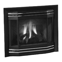
6. Pull off the pilot cap to expose the pilot
orice.
Remove the 2 screws, push Burner Assembly
to the left and lift out.
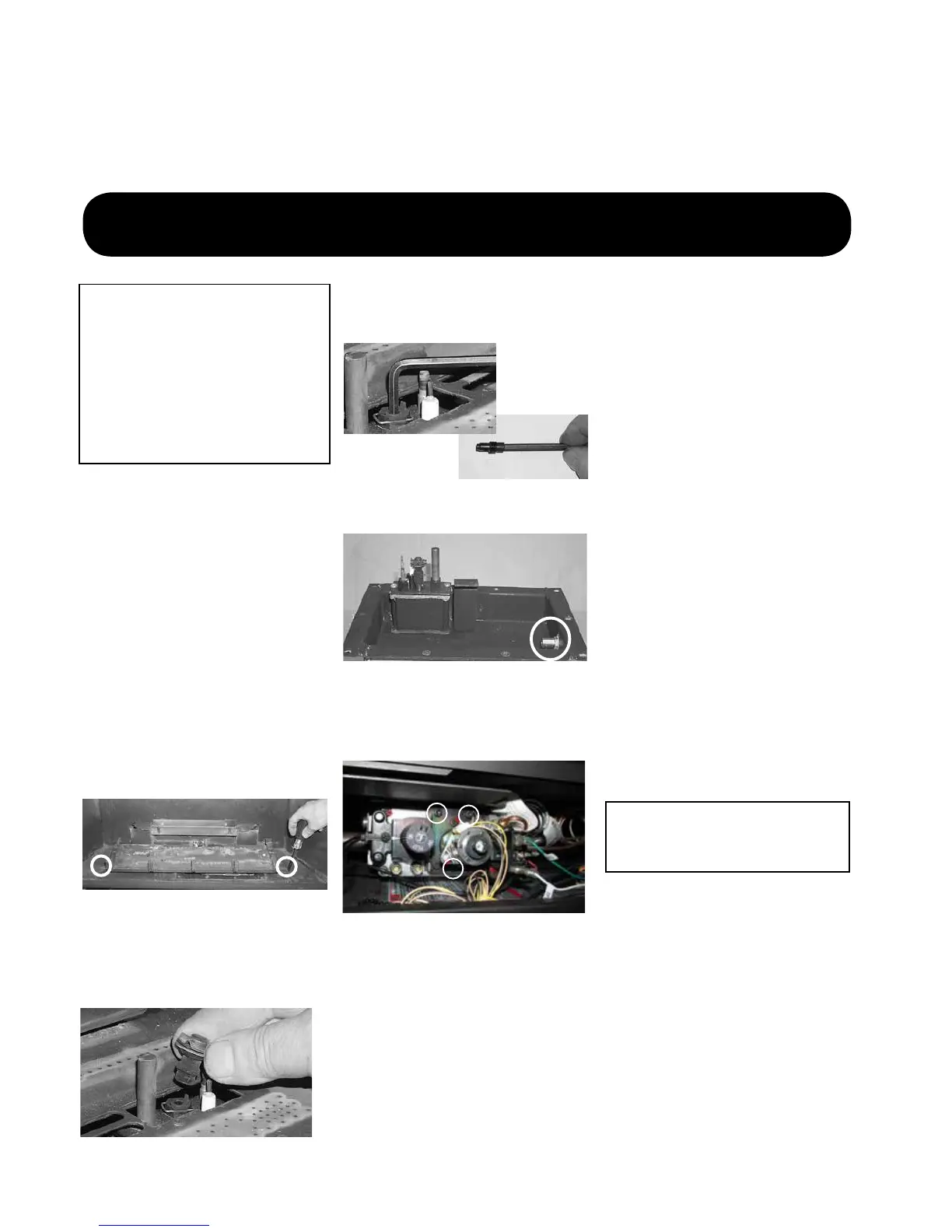
7. Unscrew the pilot orice with the allen
key; then replace with the LPG pilot
orice and the pilot cap, provided in the
kit.
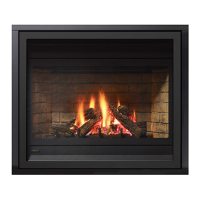
8. Remove burner orice with a 1/2"
wrench. Use another wrench to hold on
to the elbow behind the orice. Discard
orice.
9. Reinstall new burner orice LPG
stamped #52 and tighten.
Burner Orice
Conversion Kit Contains:
Qty. Part # Description
1 904-390 Burner Orice #52
1 904-529 5/32" Allen Key
1 918-590 Decal "Converted
to LPG"
1 908-528 Red "LPG" label
1 910-037 LPG Injector
(Pilot Orice)
1 910-582 Stepper Motor
1 919-472 Instruction Sheet
Installation of LPG
Conversion Kit:
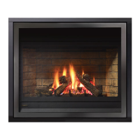
10. Remove NG stepper motor by removing
3 screws in locations shown below–re-
place with LP stepper motor, secure in
place with 3 screws.
Remove NG Stepper motor and
replace with LP Stepper motor
Installer Notice:
These instructions must be left
with the appliance.
11. Check for gas leaks with a proper soapy
solution or leak detector.
12. Check for proper spark between the
ignitor and pilot cap. Refer to "Lighting
Procedure" section of the manual for
lighting sequence.
13. Check pilot flames. Correct flame pattern
has 3 strong blue flames. Adjustment
can be made by turning the slotted
screw at the top right corner of the valve.
Refer to "Maintenance Instructions"
section of the manual for correct flame
patterns.
14. Check inlet (11" WC min) and outlet (10"
WC) pressures. Refer to "Gas Pipe Pres-
sure Testing" section of the manual.
15. Reverse Steps 5 to 1.
16. Attach the label "This unit has been con-
verted to LP" near or on top of the serial
# decal.
17. Replace yellow "NG" label with red "LP"
label.
18. Check operation of flame control.
19. Check for proper flame appearance and
glow on logs.