12
2.2.3a Before the system is switched on, the following settings
have to be carried out:
- Balancing valve (BV) set to fully open as per recommendations on
the instruction leaflet supplied with the compact mixer
- Thermostatic inlet valve (TIV) set to design flow temperature
- High limit stat (HLS) set 15ºC above design flow temperature (function
explained in the section 2.2.1 Temperature Safety Options)
- The compact mixer must be in position on the manifold before the
electrical connections can be made
- The pump live (brown) connects to the ‘L’ terminal of the secondary
pump connection inside the control centre
- The neutral wire (blue) connects to the ‘N’ terminal of the secondary
pump connection inside the control centre
- The earth wire (green & yellow) connects to the ‘E’ terminal next to the
boiler connection inside the control centre. (See Fig. 12, see page 16).
If the system is wired correctly, the pump should only run if there is a
demand signal, i.e. a room sensor (RS) activates an actuator (AC).
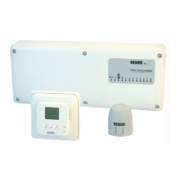
Circulating Pump
Make Grundfoss 25-60 130 (May Vary)
Overall dimensions 140mm x 95mm x 130mm (H x W x L)*
Voltage 230v
High Temperature Limit Sensor
Make Oreg TT 90
Overall dimensions 90mm x 40mm x 60mm (H x W x L)*
Temperature range +20°C to +90°C
Wiring 1.6m, 3 core flex (0.75mm²)
Balancing Valve
Type Up-and-over ½" or ¾" Female-male
Overall dimensions 60mm x 40mm (H x L)*
Material Brass MS 63 (Body)
Thermostatic Inlet Valve
Material Brass MS 63 (Body)
Temperature range +20°C to +50°C (different range on request)
System pressure 10 bar
Differential pressure 1 bar (for system differential pressures greater
than this, install pressure reducing valves prior to
the thermostatic valve)
Temperature Gauge
Temperature Range 0°C to +80°C
* Dimensions are approximates only
2.2.4 Thermostatic Mixing Valve (TMV)
- Suitable for all applications, below 30Kw. Above this weather
compensation is recommended
- Use the correct size of mixing valve (according to required heat
output: 15kW / 20kW or 30kW)
- The circulating pump only circulates the warm water through the
circuits. A separate main system pump is needed to supply the
mixing valve with hot water from the boiler.
2.2.5 Working Principle
The boiler temperature main system flow enters the thermostatic
mixing valve at 70ºC+ and is mixed with the cooler return water
from the circuits as required.
A circulating pump (CP) circulates water at the required design flow
temperature through the circuits via the manifold flow header every
time there is a demand signal from one of the room sensors. On the
return from the circuits water is taken as required, and mixed with
the main system flow. The remaining water is then routed back to
the boiler.
A wax capsule inside the thermostatic mixing valve (TMV)
expands and contracts with a temperature increase or decrease
of the mixed water inside the valve. The pre-set design flow
temperature on the valve is mechanically transformed into a
pre-stop for the valve position. This means, that no more water
from the main system flow can enter the circuits, once the
correct flow temperature is reached. A so called ‘closed’ circuit
or loop is created between the thermostatic mixing valve (TMV),
the circulating pump (CP) and the manifold with its floor heating
circuits.
If the flow temperature falls below the design flow temperature,
the thermostatic mixing valve (TMV) allows additional water from
the main system to flow into the circuit. The amount of water
added is dependent on the temperature decrease, in certain
cases the thermostatic mixing valve (TMV) can fully open the
main system flow port and fully close the return flow port. This
will result in a quick response from the FH system to sudden
increases in heat demand.
FIXED FLOW TEMPERATURE CONTROL
FIXED TEMPERATURE MIXING OPTIONS
2.0
2.2