CONTROL SYSTEM SECOND FIX
ELECTRICAL CONNECTION
5 . 0
5.2
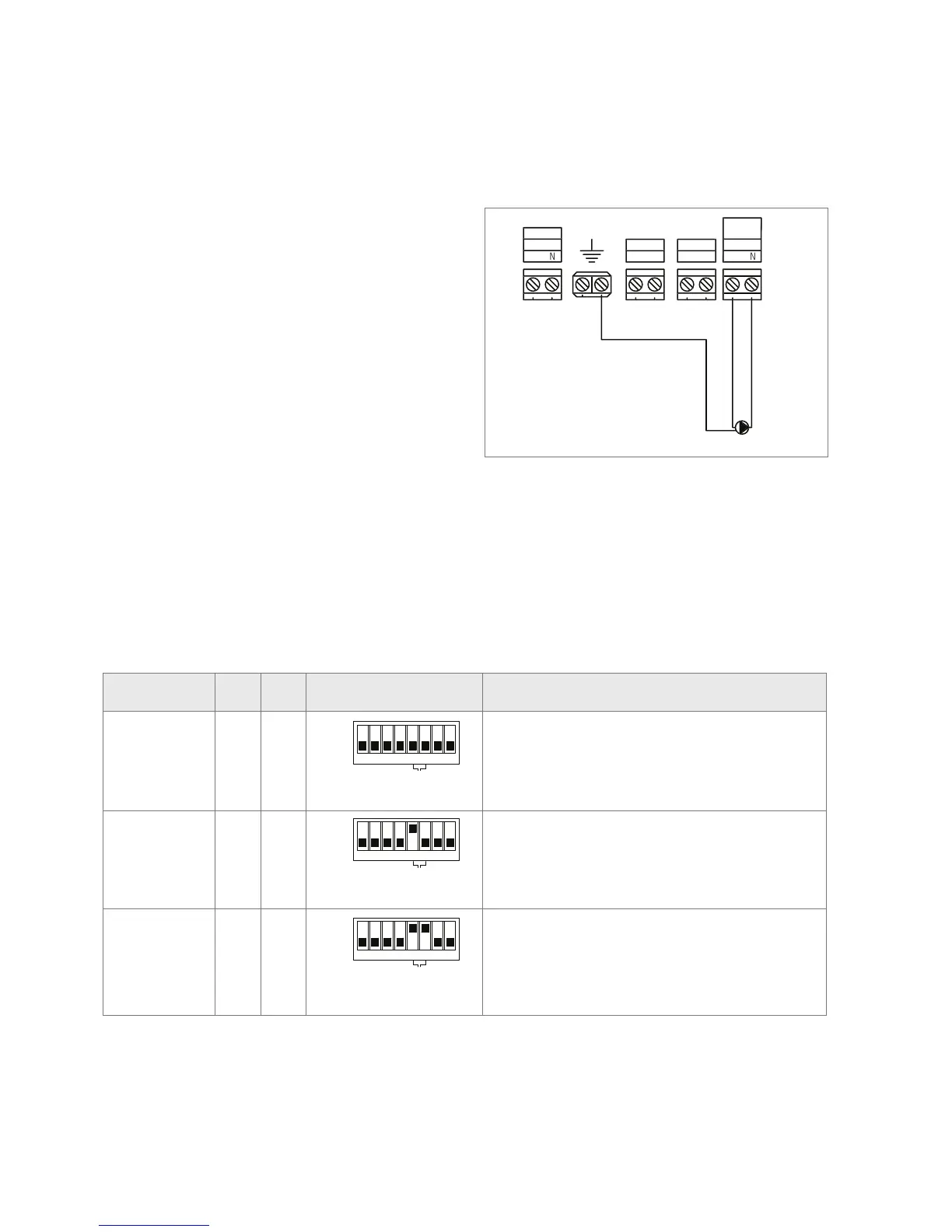
24. UFH pump output on BA Master Controller
5.2.2 Pump Outputs - UFH Pump
The master has an output for the underfl oor circulating pump (secondary
pump). The output will be energised with a delay of 180 sec after the
demand from the room sensor. The delay is to allow time for the thermal
actuator to open.
The 230v AC pump can be connected directly to terminals L and N under
the heading “Sec. UFH Pump”. Connect the pump E (Earth) terminal to E
(earth) on the master. The maximum pump load must not exceed 4 amps,
230v at start up. There is an overrun period of 1 minute after the demand
for heat from the room sensor disappears.
Delay times: Secondary UHF pump 3 min.
X-output: (confi gured as main pump) 3 min 10 sec.
X relay Output
BA controller has a relay which can be utilized for a number of different
purposes. The relay is a volt free output and is positioned on the PCB
as shown on the drawing. The function of the relay is determined by the
setting of the DIP-switches. The functions that the relay can perform, and
the appropriate DIP-switch settings, are as follows:
To control DIP - 5 DIP - 6 DIP switches
(located on the master controller)
Description
Main Pump Off Off
ON
OFF
1 2 3
4 5
6
7
8
INSTALL MODE
BOILER TEST
X - RELAY
DEHUMIDIFIER
DIP SWITCHES
RESERVED
ON
OFF
1 2 3
4 5
6
7
8
INSTALL MODE
BOILER TEST
SENSOR CHECK
INITIAL HEAT UP
SEQUENCE
X - RELAY
DEHUMIDIFIER
DIP SWITCHES
RESERVED
DIP Switches on the master controller
DIP Switch 4 turned to 'ON' on the master controller to start
initial heat up sequence in accordance with BS EN 1264
SENSOR CHECK
INITIAL HEAT UP
SEQUENCE
X RELAY Output
ON
OFF
1 2 3
4 5
6
7
8
ON
OFF
1 2 3
4 5
6
7
8
ON
OFF
1 2 3
4 5
6
7
8
X - RELAYX - RELAYX - RELAY
Where a boiler primary pump is required to be switched on from the master,
the X relay output can be used for this purpose. This relay will be activated 10
seconds after the UFH circulating pump has started
High limit zone valve On Off
ON
OFF
1 2 3
4 5
6
7
8
INSTALL MODE
BOILER TEST
X - RELAY
DEHUMIDIFIER
DIP SWITCHES
RESERVED
ON
OFF
1 2 3
4 5
6
7
8
INSTALL MODE
BOILER TEST
SENSOR CHECK
INITIAL HEAT UP
SEQUENCE
X - RELAY
DEHUMIDIFIER
DIP SWITCHES
RESERVED
DIP Switches on the master controller
DIP Switch 4 turned to 'ON' on the master controller to start
initial heat up sequence in accordance with BS EN 1264
SENSOR CHECK
INITIAL HEAT UP
SEQUENCE
X RELAY Output
ON
OFF
1 2 3
4 5
6
7
8
ON
OFF
1 2 3
4 5
6
7
8
ON
OFF
1 2 3
4 5
6
7
8
X - RELAYX - RELAYX - RELAY
This function is used where an additional protection is required to prevent boiler
water entering the underfl oor system. When the system is off or when the
supply water exceeds 65°C. An additional fl ow water temperature sensor
(ETF-1899A) and a zone valve are connected (Fig. 14)
Cooling device or
module alternative
On On
ON
OFF
1 2 3
4 5
6
7
8
INSTALL MODE
BOILER TEST
X - RELAY
DEHUMIDIFIER
DIP SWITCHES
RESERVED
ON
OFF
1 2 3
4 5
6
7
8
INSTALL MODE
BOILER TEST
SENSOR CHECK
INITIAL HEAT UP
SEQUENCE
X - RELAY
DEHUMIDIFIER
DIP SWITCHES
RESERVED
DIP Switches on the master controller
DIP Switch 4 turned to 'ON' on the master controller to start
initial heat up sequence in accordance with BS EN 1264
SENSOR CHECK
INITIAL HEAT UP
SEQUENCE
X RELAY Output
ON
OFF
1 2 3
4 5
6
7
8
ON
OFF
1 2 3
4 5
6
7
8
ON
OFF
1 2 3
4 5
6
7
8
X - RELAYX - RELAYX - RELAY
The relay output can be used to provide a volt free signal to a heat pump or to a
K-MOD switching module where a chiller is utilized to provide the cooling water.
The relay output is always on in cooling mode and off in heating mode.
(Refer to Fig. 38a, see page 41)