58
SPECIAL FUNCTIONS
DIP SWITCHES
12.0
12.2
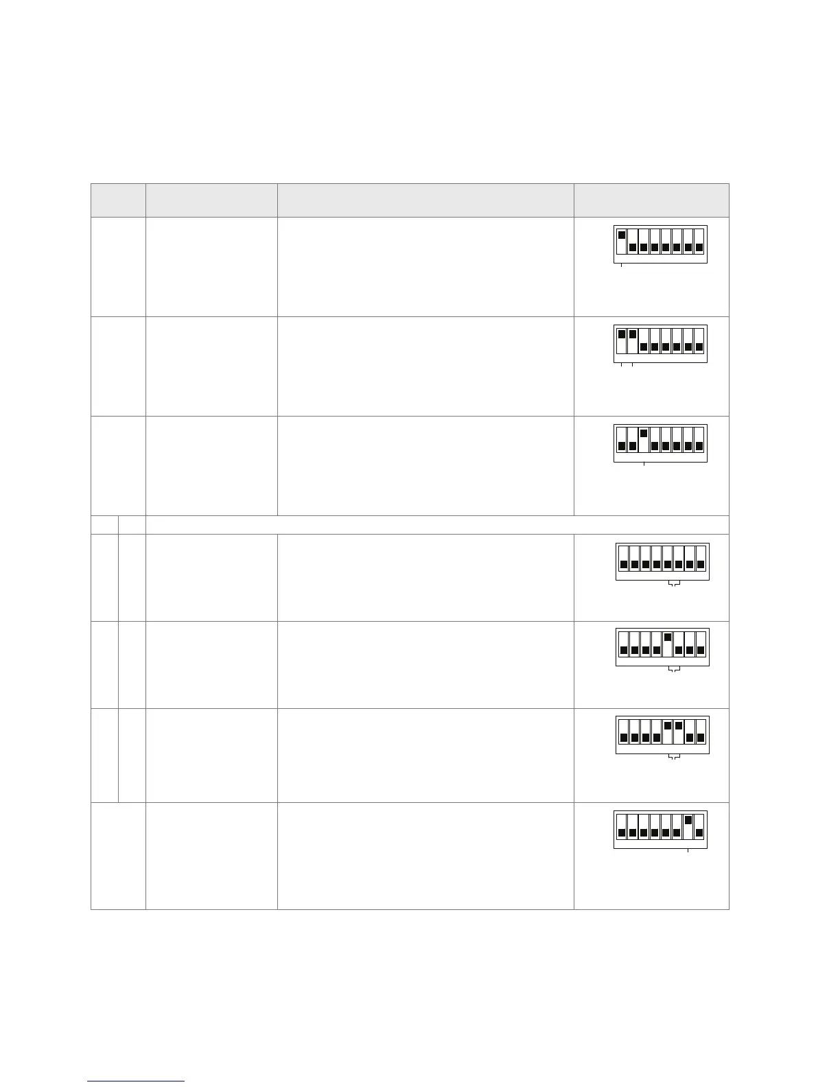
DIP Switch Function Description DIP switches
(located on the master controller)
1 Turn on to activate install mode Increase temperature on sensor in room 1, this would activate actuator on
output 1 and will open after 1-3 minutes, UFH pump to turn on and mixing valve
to open; Turn off to deactivate
ON
OFF
1 2 3
4 5
6
7
8
INSTALL MODE
1 & 2 Turn on to close boiler relay This closes the boiler start relay contacts for 1 minute; Turn off to deactivate
ON
OFF
1 2 3
4 5
6
7
8
INSTALL MODE
BOILER TEST
3 Turn on to activate learn mode Power light start blinking; each red channel light on master should now be lit if a
room sensor is present on that channel. Turn off to deactivate
ON
OFF
1 2 3
4 5
6
7
8
SENSOR CHECK
5 6
Off Off Main Pump Where a boiler primary pump is required to be switched on from the master,
the X relay output can be used for this purpose. This relay will be activated 10
seconds after the UFH circulating pump has started.
ON
OFF
1 2 3
4 5
6
7
8
INSTALL MODE
BOILER TEST
X - RELAY
DEHUMIDIFIER
DIP SWITCHES
RESERVED
ON
OFF
1 2 3
4 5
6
7
8
INSTALL MODE
BOILER TEST
SENSOR CHECK
INITIAL HEAT UP
SEQUENCE
X - RELAY
DEHUMIDIFIER
DIP SWITCHES
RESERVED
DIP Switches on the master controller
DIP Switch 4 turned to 'ON' on the master controller to start
initial heat up sequence in accordance with BS EN 1264
SENSOR CHECK
INITIAL HEAT UP
SEQUENCE
X RELAY Output
ON
OFF
1 2 3
4 5
6
7
8
ON
OFF
1 2 3
4 5
6
7
8
ON
OFF
1 2 3
4 5
6
7
8
X - RELAYX - RELAYX - RELAY
On Off High limit zone valve This function is used where an additional protection is required to prevent
boiler water entering the underfloor system. When the system is off or when
the supply water exceeds 65°C. An additional flow water temperature sensor
(ETF-1899A) and a zone valve are connected (Fig. 14, see page 17)
ON
OFF
1 2 3
4 5
6
7
8
INSTALL MODE
BOILER TEST
X - RELAY
DEHUMIDIFIER
DIP SWITCHES
RESERVED
ON
OFF
1 2 3
4 5
6
7
8
INSTALL MODE
BOILER TEST
SENSOR CHECK
INITIAL HEAT UP
SEQUENCE
X - RELAY
DEHUMIDIFIER
DIP SWITCHES
RESERVED
DIP Switches on the master controller
DIP Switch 4 turned to 'ON' on the master controller to start
initial heat up sequence in accordance with BS EN 1264
SENSOR CHECK
INITIAL HEAT UP
SEQUENCE
X RELAY Output
ON
OFF
1 2 3
4 5
6
7
8
ON
OFF
1 2 3
4 5
6
7
8
ON
OFF
1 2 3
4 5
6
7
8
X - RELAYX - RELAYX - RELAY
On On Cooling device or module
alternative
The relay output can be used to provide a volt free signal to a heat pump or
to a K-MOD switching module where a chiller is utilized to provide the cooling
water. The relay output is always on in cooling mode and off in heating mode
ON
OFF
1 2 3
4 5
6
7
8
INSTALL MODE
BOILER TEST
X - RELAY
DEHUMIDIFIER
DIP SWITCHES
RESERVED
ON
OFF
1 2 3
4 5
6
7
8
INSTALL MODE
BOILER TEST
SENSOR CHECK
INITIAL HEAT UP
SEQUENCE
X - RELAY
DEHUMIDIFIER
DIP SWITCHES
RESERVED
DIP Switches on the master controller
DIP Switch 4 turned to 'ON' on the master controller to start
initial heat up sequence in accordance with BS EN 1264
SENSOR CHECK
INITIAL HEAT UP
SEQUENCE
X RELAY Output
ON
OFF
1 2 3
4 5
6
7
8
ON
OFF
1 2 3
4 5
6
7
8
ON
OFF
1 2 3
4 5
6
7
8
X - RELAYX - RELAYX - RELAY
7 Turn on for Dehumidifier If a dehumidifier is being used it can be connected via a relay using number
1 output on the master and setting DIP-7 to “on”, the output given is 24V ac.
Hence Channel 1 cannot be used for room temperature control
ON
OFF
1 2 3
4 5
6
7
8
DEHUMIDIFIER