19
2.3.3 Dew Point Control
The dew point control of the system is performed by the BA Master Controller coupled with
the Humidity sensors positioned within the index rooms (refer section 4.2). The controller
will calculate the dew point temperature based on the index room temperature and the
% of relative humidity within the index room. If the system has more than one humidity
sensor installed within the control system then the BA Master Controller will operate to
the worst case temperature and humidity conditions. If the cool water temperature flowing
into the floor heating/cooling circuit approaches the dew point temperature (safety factor
of 2°C), the controller will signal the actuators present on the manifold to close the return
valve of the circuits and there by preventing the formation of any condensation.
2.3.4 Installation
Required Components Qty
Supplied
by REHAU
High Limit Sensor
(strap-on or phial pocket/well)
1x Yes
Wiring
No wiring work is required if a REHAU Compact Mixer Unit is used.
All other Systems:
- The pump live (brown) wire should be connected to terminal (1) within the HLS
- The 2-Port zone valve live (brown) wire should also be connected to this terminal
- The live (Brown) wire to the high limit sensor is connected to terminal (C) within the
HLS and must be supplied from the ‘L’ terminal of the sec pump connection inside the
control centre. (As shown in Fig. 13)
Note: Please refer to page 16 for wiring diagram.
Data
Strap on:
Dimensions : 92mm x 48mm x 77mm (H x W x D)
Setting range : 25ºC to 95ºC
Switch type : SPDT
Switching Differential : Adjustable from 4K to 10K
Max Ambient Temperature : 70ºC
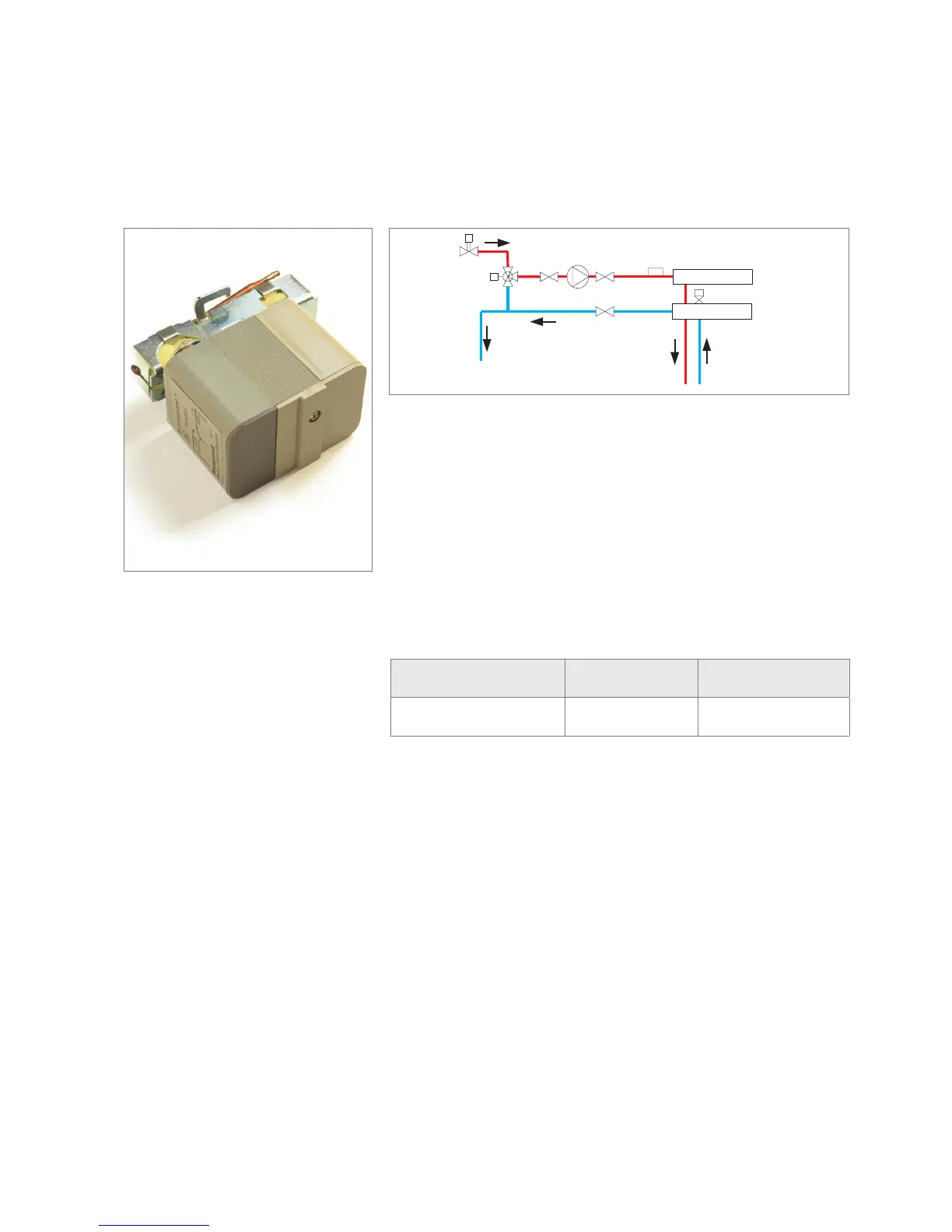
2.3.1 High Limit Sensor (HLS)
2.3.2 Working Principle
The sensor of the high limit sensor (HLS)
monitors the mixed flow temperature.
This is a safety device, which should be set to a
temperature of 15ºC above the max. design flow
temperature. In the case of a system malfunction
and the max. design flow temperature being
exceeded, the high limit sensor (HLS) switches
off the secondary circulating pump (CP), and cuts
the power to the zone valve. With the zone valve
closed and the circulating pump stopped, no hot
water can enter the floor heating circuits.
Fitting
(Always read and follow instructions supplied
with components)
- If a REHAU compact mixer unit is used, the high
limit sensor (HLS) is already pre-assembled
- Check high limit is set for 15°C above
required set point
- For all other systems the high limit sensor (HLS)
must be fitted after the circulating pump (CP)
and before the manifold flow header. It should
also be fitted at least 0.3m to 0.5m after the
mixing valve.
Recommended Position for HLS


 To Next Page