57
SPECIAL FUNCTIONS
NETWORKING MULTIPLE CONTROLLERS
12.0
12.1
In larger buildings with more than 14 zones where multiple manifolds are utilised, it is possible to use multiple masters to create a
single network. One master must be defined as the “network controlling master” by setting both dials to zero (see table below).
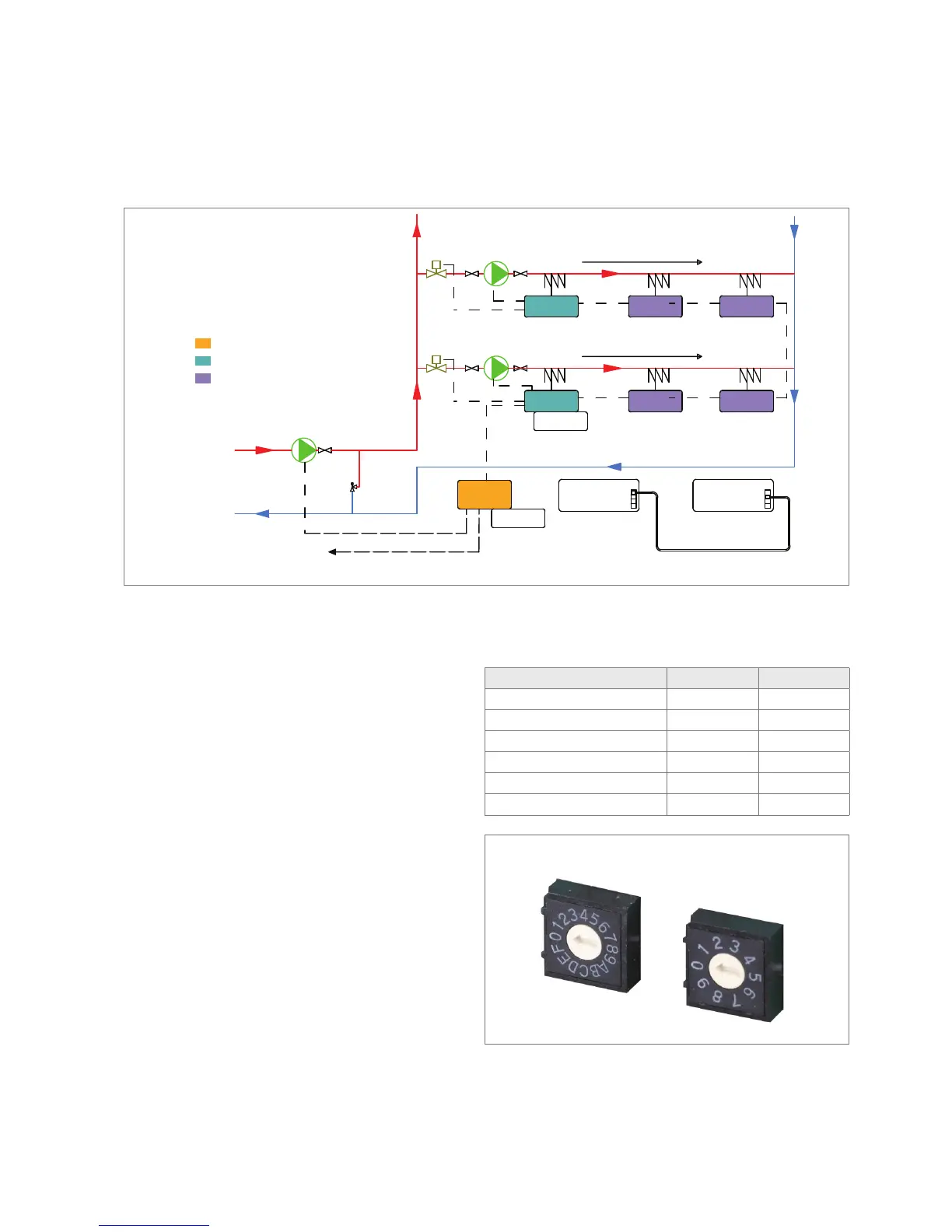
50. Hydraulic Schematic for Networking of Multiple Controllers
Left Dial Right Dial
Using more than one secondary pump
1. If more than one secondary pump is used, a separate string should
be created for each pump (see Fig. 50). On the first string all left hand
dials in the slaves must be set to 1, and the right hand dial should
be set in sequence from 1 to 9. On the second string of masters/
slaves all left hand dials should be set to 2 and the right hand dials
again should be set in sequence from 1 to 9. This numbering can be
continued for up to 15 strings.
2. All main controllers are interconnected using special cable via the
RJ 45 socket 1 or 2.
3. RJ 45 connection of string 1 to string 2 etc., can be achieved
via string 1 slave to string 2 submaster or string 1 slave to string 2
slave as shown in Fig.50.
4. An BA Master Controller can be used as the “network
controlling master” for central mixing control of supply water and
boiler switching.
Master and Slave Left dial set to Right dial set to
Network Controlling Master 0 0
String 1 Submaster 1 1
String 1 Slave 1 2 to 9
String 2 Submaster 2 1
String 2 Slave 2 2 to 9
Up to String 15 Submaster 1 to F 1