54
DOMESTIC HOT WATER (DHW),
RADIATORS AND TWO STAGE CONTROLLER
DOMESTIC HOT WATER (DHW)
11.0
11.1
Working Principle
The REHAU CT2/HW is provided with a remote flow temperature sensor
which is strapped on to the domestic hot water supply pipe from the
cylinder (within 150mm of top of cylinder). The temperature of the hot
water is controlled by REHAU CT2/HW, which continuously compares the
required water temperature with actual water temperature measured by
the flow temperature sensor. If the water temperature is too low, it will
signal the zone valve (wired via a 24V Relay into the Master Controller)
to open and start the boiler there by allowing hot water to flow through
the primary coil.
Programming
The programmable function allows for two timed periods per day
when the water temperature is generated up to the level set within the
controller. Outside of these periods a second temperature can be set,
as a back up, below which the stored hot water is not allowed to fall,
outside of the timed periods. The actual temperature being measured
by the sensor is displayed in the controller’s “info” menu.
Default Settings** Description
50ºC* Hot water generation
30ºC Back up water temperature not allowed to
fall below the set temperature
* This may be reduced to a lower setting if solar generation of hot water is employed, so
that best use is made of the “free” energy produced by the solar heating
** For altering the default settings please refer to Section 10, on page 45
Installation
A 2-port zone valve is installed on the primary supply from boiler
to storage cylinder, and this is wired to a 24V Relay, which is
controlled by the output of the REHAU BA controller. The channel
output number is set in the REHAU CT2/HW controller.
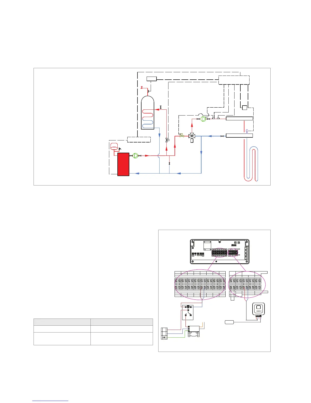
Boiler
Constant Flow Water Temperature system with 'S' plan Integration
CP
TMV
TS
ZV
Manifold Flow Header
Manifold Return Header
ZV
AV
BPV
PV
CP
CP
RS
Junction Box
BA Master Controller
CT2/HW
Hot Water Sensor
HWS
Hot Water
Cylinder
HLS
HWS
CT2/HW
SV
ZV
HLS
AV
TS
CP
BPV
SV
PV
CS
RS
TMV
Hot Water Supply
Domestic Hot Water Controller
Safety Valve
Zone Valve
High temperature Limit Thermostat
Air Vent
Temperature semsor (Flow)
Circulating Pump
By pass Valve
Safety Valve
Pressure Vessel
Cylinder Sensor
Room Sensor
Thermostatic Mixing Valve
THERMAL ACTUATORS 24V
L N L L L L LN N N N N
Out put 1
L N L L L L LN N N N N
THERMAL ACTUATORS 24V
L LN N
L LN N
SWITCH
EXT.
I O
+ +
TT
LINK
DISPLAY
L YN X
SUPPLY
SENSOR
SENSOR BUS
+
T
+
T
APP
SENSOR
SENSOR BUS
MIXING VALVE
0 - 10V
MIXING VALVE 24V AC
+
T
Out put 2 Out put 3 Out put 4 Out put 5 Out put 6 Out put 7 Out put 8
Out put 1 Out put 2 Out put 3 Out put 4 Out put 5 Out put 6 Out put 7
Out put 8
24 V RELAY
A1
A2
11
14
no
12
nc
ZONE VALVE ON DHW CIRCUIT
LNEARTH
Master Controller
NETWORK BUS
NETWORK BUS
ADD-ON
MODULE
WIRELESS
RECEIVER
RJ45
NOT USED
LN
230V AC
Mains
Supply
Brown
Blue
Green/ Yellow
Orange
Grey
REHAU CT2/ HW
Controller
REMOTE SENSOR FOR
HOT WATER CYLINDER
Channel Selector
Set to Output 5
REHAU
T T
+ +