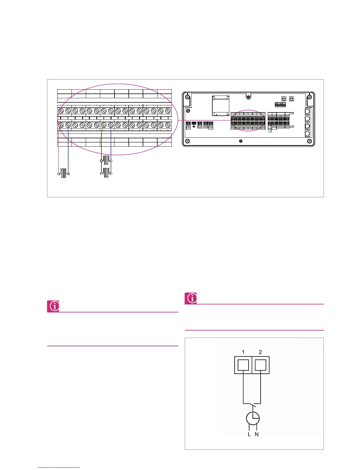
28. Actuator connection to Master Controller
29. Connection of external switch/ timer located on the Master Collection
TIMER. EXTERNAL SWITCH
VOLT FREE
CONTACTS
5.2.5 Connecting Thermal Actuators (TH 1 – TH 8)
Maximum 14 x 24 Volt actuators per controller.
Ensure that the actuators are connected to the correct zone.
Actuators controlled by zone 1 must be connected to output
terminal 1 (TH 1) etc.
Connect one wire from the actuator to right hand terminal on the
respective zone output terminal block (TH 1-TH 6) then connect the
other wire from the actuator to the left hand terminal block. These
terminal blocks are not polarity sensitive.
A maximum of 4 actuator heads can be installed into each
output, 2 terminal blocks, 14 actuator max. per controller
within the controller as long as they are to be controlled by
the same sensor.
5.2.6 External Switch/Timer
The controllers can accept a volt free signal from an external switch /
timer which will facilitate the switching between day mode and night
set back mode only. For setback the switch will be in OPEN circuit and
CLOSED for day- time operation. Each controller type comes fitted
with a link across the Ext switch. This link has to be removed and
replaced with the switch/timer connection all other system parameters
will have to be programmed into either a REHAU CT2 Programmable
Room Sensor. No system programming is available with the REHAU BA
controller. (See section 8.1 System Start Up & Operating Instructions).
Connection of the external switch/timer will override the
settings of any CT2 Programmable Room Sensors installed onto
the system.