22
Other installation sites
The following are also suitable installation
sites for suction and exhaust air pipes:
■ Unused chimney flues
■ Wall slots
■ Hollow-beam ceilings
■ Compensating ballasts
■ Spaces between layers of insulation
■ Elevated floors
■ Lightweight walls
Sweat water formation
Sweat water will form in the pipelines in non-
stainless areas.
For this reason, provide all pipelines in the
building in which sweat water will form with
diffusion-proof insulation material.
Closed-cell materials with high water vapour-
diffusion resistance are suitable for this. If
open-cell of fibrous insulation materials are
used, they must have an impermeable outer
layer that is firmly attached to the insulation
material.
➜ Close off impact, groove, cut and end
points with a permanent seal.
➜ Cut out insulation in the area of
attachment.
➜ Pull insulation material over the attached
section and permanently seal it to the
neighbouring insulation material with
adhesive.
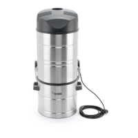
Installation information
➜ Avoid narrow radii with changes in
direction; 90º bends only immediately
behind the suction sockets.
➜ Along the rest of the pipe, use two 45°
bends or 45° branches with less flow
resistance (see Fig. 5-15).
Fig. 5-15: Installation example
➜ Shorten pipes with a fine-tooth saw and a
mitre box for a right-angle cut.
➜ Deburr the cut area and lightly bezel it to
get rid of edges which could catch debris,
dust or threads.
➜ In unheated rooms, insulate the pipelines
to prevent condensation water from
forming.
➜ Clean the O-ring, sleeve interior and
pointed end before connecting the pipes.
➜ Apply a sliding agent to the pointed end to
facilitate installation.
➜ When installing the vacuum pipes, ensure
that the sleeve is always pointing against
the direction of flow.
➜ To protect against penetrating debris, e.g.
when plastering, vacuum pipes laid under
plaster are to be covered with a protective
sheath or the sleeve gaps are to be closed
with tape.
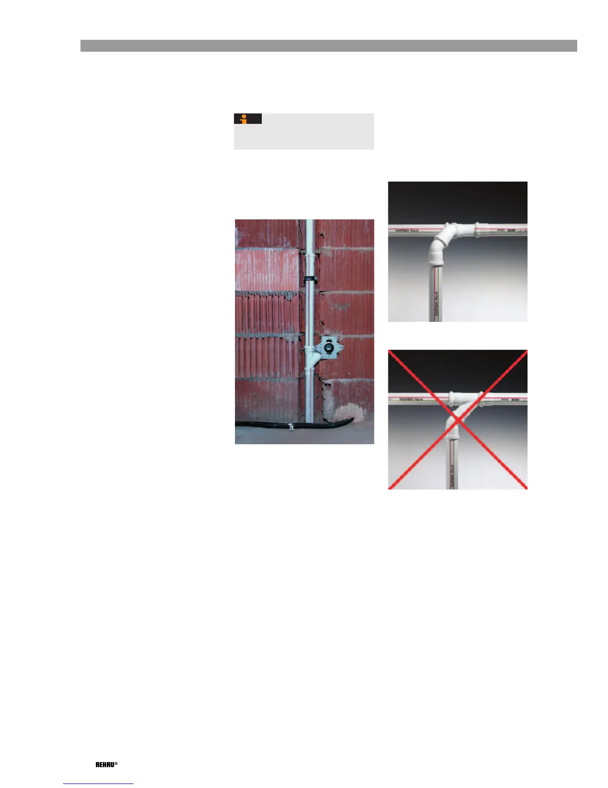
➜ Install branches upward or to the side only,
so that debris in transit does not fall into
the suction pipe below (see Fig. 5-16 and
Fig. 5-17).
Fig. 5-16: Downward branch – installed
properly
Fig. 5-17: Downward branch – installed
incorrectly
➜ If a suction socket must be installed below
the suction pipe, first install the branch
horizontally and then lead it downward
with two 45° bends (see Fig. 5-16).
A gradient need not be provided for
horizontal sections of the suction pipe.
 Loading...