16
5.2
Suction socket
➜ Install suction sockets at the same height
as the electrical outlets for a pleasing
appearance.
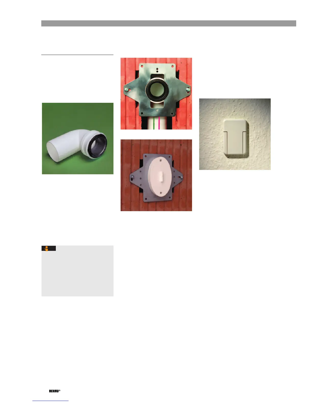
➜ Install suction socket connecting bend
DN 50 90° (Item No.: 243558-002,
minimum installation depth is approx.
90 mm (see Fig. 5-1)) with the sleeve flush
with the masonry.
Fig. 5-1: Suction socket connecting bend
➜ Pull the suction socket adapter (black
rubber nipple, Item No. 243578-001) out
of the suction socket connecting bend.
➜ Attach suction socket connecting bend
onto the back of the mounting frame (Item
No. 243352-001) in such a way that the
holding plate runs in the groove of the
bend.
➜ Insert the pointed end of the connecting
bend into the sleeve of the suction pipe
running in the wall slot.
➜ Secure mounting frame vertically in the
wall.
➜ Reinsert suction socket adapter.
Fig. 5-2: Installed mounting frame
Fig. 5-3: Mounting frame with plaster
cover
➜ In order to plaster, attach the plaster cover
(Item No.: 242767-001) (see Fig. 5-3).
➜ To remove the plaster cover, insert a
narrow screwdriver into the slot, press the
clip toward the central bridge and pull off
plaster cover.
➜ Apply a sliding agent to insertion end of
suction socket (Item No. 128933-002) and
press into the suction socket adapter.
➜ Screw in and tighten socket at mounting
frame (Cover opening faces upward or
downward).
Fig. 5-4: Fully installed suction socket
The alignment of the suction socket is
defined by the vertical mounting of the
mounting frame.
The opening direction of the suction
socket cover is determined by the
installation direction of the mounting
frame (see mounting instructions of the
mounting frame (Brochure No.
00F2075 d,e,f)).
 Loading...