9
2. Planning
2.1
Planning information
Warning!
Risk of death!
Disregarding the fire-protection
regulations and measures risks death and
severe burns to users/tenants.
➜ Observe fire-protection regulations and
building codes of practice/regulations.
■ It is not necessary to provide each
room with a suction socket. The
required number is determined during
the planning phase.
■ The vacuum pipes may be mounted
on or inside the wall.
➜ Lay the pipe system as short and
straight as possible.
➜ Install the suction sockets near doors
so as to cover several rooms. This
installation location also ensures that
the suction sockets are not blocked by
furniture.
➜ For garages, install suction sockets
near the garage door so that you can
clean your car comfortably outside the
garage.
➜ Take an under-roof floor which can be
finished into account during planning
and execution.
2.2
Planning stages
1. Acquire correct-scale ground plot
diagrams of the building (scale 1:100).
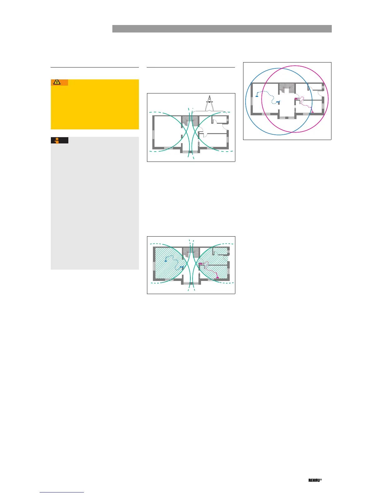
Fig. 2-1: Drawing ranges
2. Draw the ranges (green lines) on the
ground plot diagrams (see Fig. 2-1):
- Determine the working radius: For this
purpose, deduct 1 m from the length of
the suction hose.
Length of the suction hose:
6 m for Item No. 242483-001,
8 m for Item No. 242473-001.
- Draw the working radius from the outer
corners of the ground plot with the
compass.
Fig. 2-2: Providing suction sockets
3. Provide suction sockets in the overlap
areas (shaded green) (see Fig. 2-2):
- If two circles overlap: Install a suction
socket in each overlap area.
For optimal use of the working radius of
the suction hose: Select the final
position of the suction sockets in such a
way that the non-shaded areas are also
covered with the suction hose.
- If all the circles in a common area
overlap, e.g. in small flats, a single
suction socket is sufficient for each flat:
Provide a suction socket in this area.
- If no overlap areas arise when planning
for larger structures: Provide additional
suction sockets.
Fig. 2-3: Drawing working radius
4. Draw the working radius from the planned
suction socket as a checking measure (see
Fig. 2-3):
- Check whether all areas to be cleaned
are within the working radii.
- Check whether partition walls limit the
working radius.
5. Determine the installation site of the central
vacuum unit:
- Always install the central vacuum unit
toward the bottom of the building.
- If suction occurs against the pull of
gravity in sections of the suction pipes:
Comply with the usage limitations (see
Chap. 4, Page 13).
6. Determine the design length to select the
unit type:
- The design length corresponds to the
pipeline length from the central vacuum
unit to the furthest suction socket plus
the length of the exhaust air pipe.
- Take the following equivalent lengths
into account with the design length for
each redirection (bend, branch):
45° bend: 0.5 m
90° bend: 1.0 m
Branch: 0.5 m
7. Select the central vacuum unit with the
appropriate performance using the
calculated design length (see Table 4-1,
Page 13).