2-3
Description of the PSC Console
2.3 Description of Main Components
This section describes the main components of the PSC Console shown in Figure
2.1.
2.3.1 Display
The display consists of 20 characters x 4 lines and each character consists of 5 x 7
dots.
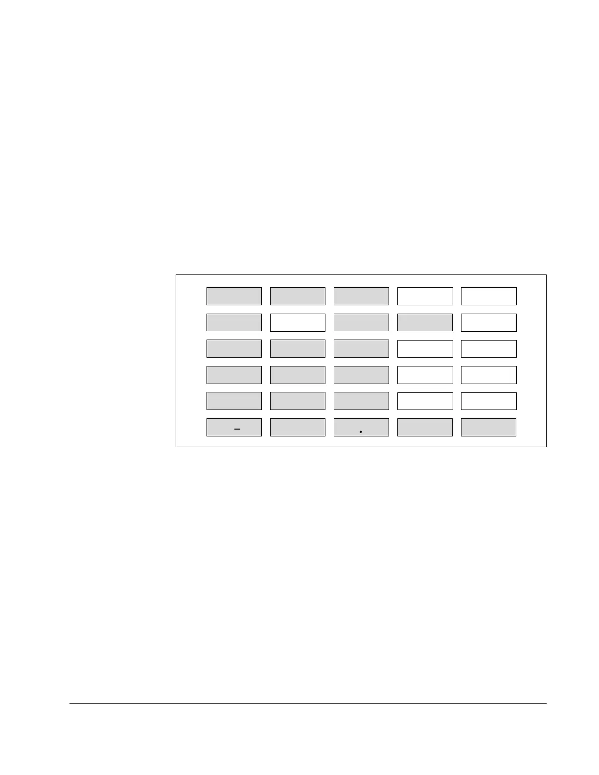
2.3.2 Keyboard
Figure 2.2 shows the key arrangement of the PSC Console keyboard. There are
two kinds of keys: usable ones for the PSC Console and unusable ones. The keys
grey-colored in Figure 2.2 are usable, and the remaining are not usable. Pressing
the unusable keys will do nothing.
RUN MONITOR
PROGRAM P-ROM SHIFT
ALLCLR VRFY MON DATA NO
123
456
789
0 CLR
C
E
PLAY
RCD
TEST
ENTER
DEL
+/
Figure 2.2 – Key Arrangement and Effective Keys
The functions of the usable keys are as follows.
Legend Description
RUN To switch the PSC Console to RUN Mode.
MONITOR To switch the PSC Console to MONITOR Mode.
PROGRAM To switch the PSC Console to PROGRAM Mode.
ALLCLR To clear errors or to move to the initial state of each mode.
MON To display control variable
DATA To display attribute data.
0 to 9 To enter numbers Naught to Nine.
+/– To switch polarity of data. Every time this key is pressed, the polarity
is switched between "+" and "–".
. To enter decimal point.
CLR To set or modify attribute data.
ENTER To confirm the data and to execute the program.
 Loading...