101
Control units VCS
PLC Controller for Compressor Output Control
Viewing Alarms
If a failure occurs during operation, this state is signalled by
a flashing symbol . Furthermore, the corresponding alarm
can be displayed. For a description, refer to point 5.2.
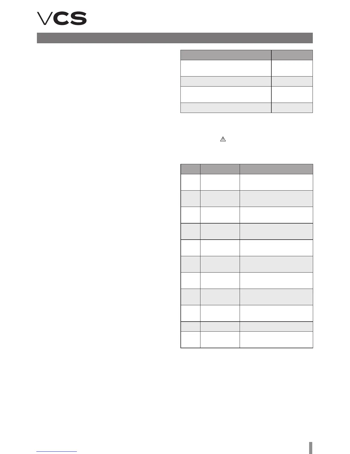
Alarm Types
Application Version Settings
One compressor with output
control, BASIC version
-1
Two compressors, BASIC version - 2
One compressor without output
control, PREMIUM version
1
Two compressors, PREMIUM version 2
Code Cause Description
A-01
LP sensor
failure
Check 4-20mA current loop.
A-02
Td sensor
failure
Check the tempera-
ture sensor.
A-03
HP sensor
failure
Check 4-20mA current loop.
A-04
Compressor
1 failure 1
Check the compres-
sor protections.
A-05
Compressor
2 failure
Check the compres-
sor protections.
A-06 HP failure
Number of HP pressostat
failures exceeded.
A-07 LP failure
Number of LP pressostat
failures exceeded.
A-08
Control sig.
failure
Check 0-10V signal.
A-09
Expanding
module failure
Expanding module
does not respond.
A-10 EEV failure Expansion valve failure.
A-11
Condenser
failure
Check the condenser
circuit breaker.
n P-17 Coolant: Used coolant type.
(0= R404A, 1=R22,2=R744, 3 = R290, 4 = R134A,
5 = R407C, 6 = R410A, 7 = R427A, 8 = R507A).
n P-32 PID HP Udz: PID control upper insensitive zone.
n P-33 PID HP Ldz: Control lower insensitive zone
n P-34 PID HP Bp: Control proportionality zone
n P-35 PID HP Ti: Control integration constant
n P-36 PID HP Td: Control derivative constant
n P-37 PID HP Arw: Control anti-reset li
n P-38 PID HP Speed: Maximum number of PID output
changes per 1 sec.
n P-40 Bypass time LP: Low-pressure pressostat
bypass time upon compressor start.
n P-41 Filter time LP: Low-pressure pressostat bypass
time when the compressor is running.
n P-42 Bypass time LPA: Low-pressure sensor failure
bypass time upon compressor start.
n P-43 Filter time LPA: Low-pressure sensor bypass
time when the compressor is running.
n P-45 Curb Enable: Output limitation enable from the
PID high-pressure controller.
n P-47 Warning time (0 to 600 sec):
Time for which the output limitation is signalled.
n P-50 PID Cond Bp: PID control proportionality zone.
n P-51 PID Cond Ti: Control integration constant
n P-52 PID Cond Td: Control derivative constant
n P-53 PID Cond Udz: PID control upper insensitive
zone.
n P-54 PID Cond Ldz: PID control lower insensitive zone
n P-55 PID Cond Speed: Maximum number of PID
output changes per 1 sec.
n P-56 PID Cond Arw: Control anti-reset li.
n P-48 Warning value (0 to 100%):
PID controller limiting value – when exceeded, the output
limitation is signalled.
n P-60 Increment time (10 to 600 sec):
Additional compressor connection time.
n P-61 Decrement time (0 to 120 sec):
Additional compressor switch-off delay time.
n P-66 Dif. through En.: Enables use of the differential
pressostat information for the cooling heat exchanger.
Anti-freeze protection. It starts defrosting.
n P-67 Swap time: Cooling/heating mode
switching time.
n P-68 Det time: Maximum defrosting time.
n P-69 Dit time: Defrosting interval.
n P-70 Switch OFF:
e compressor is switched off when switching
cooling/heating modes.
n P-71 Switch Cap.: (0 to 100%)
Compressor output between cooling/heating
mode switching.
n P-74 Defrost LP: (-10.0 to 2.5°C)
Evaporation pressure limit compared with S-00 below
when defrosting is enabled.
n P-77 Maf:
Number of cycles for the pressure oscillation mathematical
filter.
n P-79 App: Application selection.