105
Control units VCS
Commissioning Preparations
Exhaust coolant from the corresponding part of the cooling
circuit.
Warning:
e EX valve is delivered in the open position – it must be
closed before it is filled with coolant.
Connect the EC3 to 24V while the digital input I is open (0V)
– the valve will be closed.
Once the valve has been closed, the circuit can be filled with
coolant.
Warning:
Settings of the EC3 must be performed before the valve is
connected to voltage. Digital input I must not be connected
to 24V before all the parameters are set.
ECD-002 can be connected to EC3 in the G socket using
an ECC-Nxx conductor or another common Class 5 cable
equipped with RJ 45 connectors.
e basic purpose of this relay is to protect the sys-
tem when the power supply fails, if the communication
interface or ECD-002 is not used.
Digital input I operation according to com-
mands for the compressor/thermostat
It controls:
Operating
conditions
digital input
Compressor
Compressor start
closed/24V
(start)
Compressor stop
opened/0V
(stop)
ermostat
Command (com-
pressor is running)
closed/24V
(start)
No command
opened/0V
(stop)
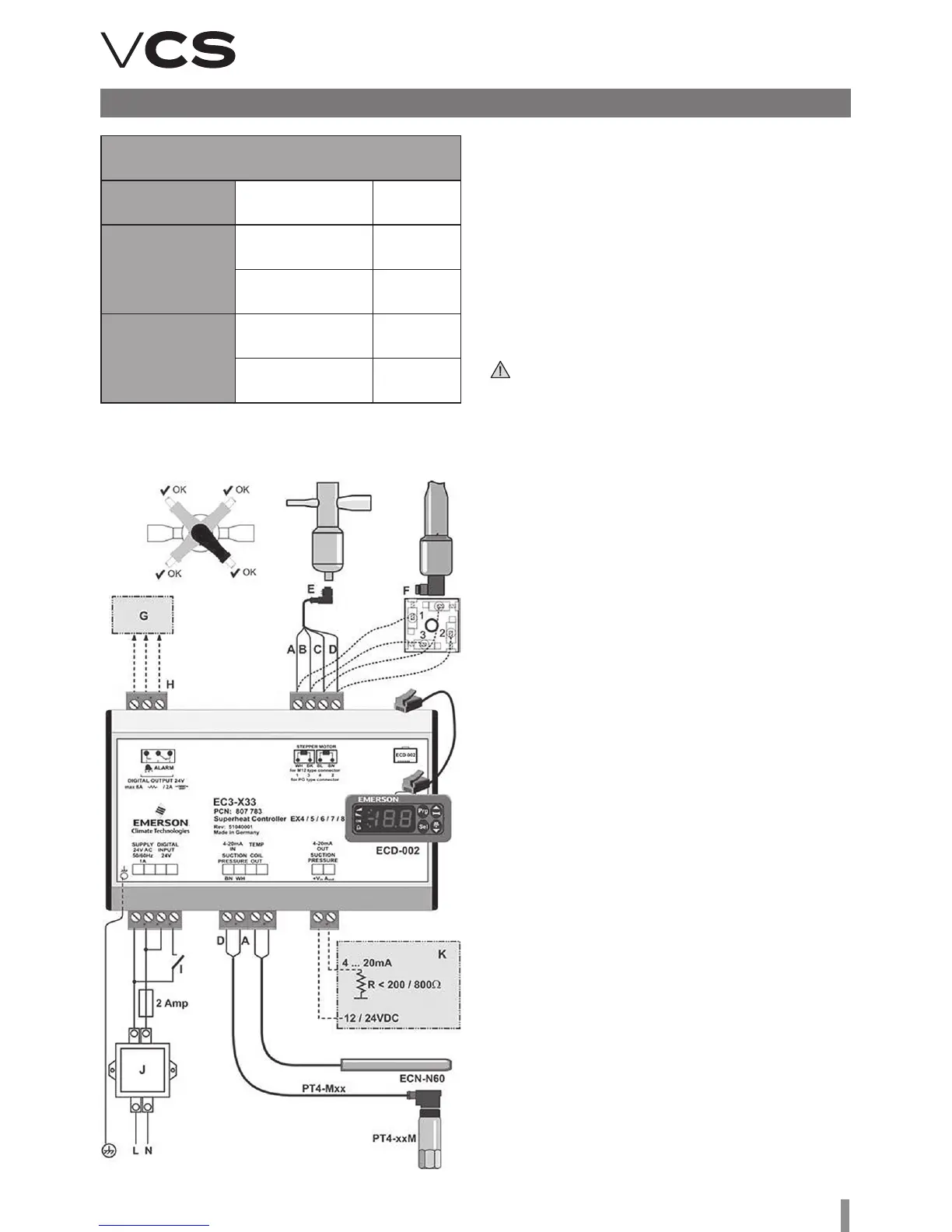
Electronic Expansion Valve Overheating Controller EC3-X33
Wiring Diagram
Conductor Marking and Purpose
E EX valve connection using terminated cable
(A white, B black, C brown, D blue)
F EX8 (respectively EX7)
valve connection – only terminal
G Auxiliary control device
H Failure relay – no voltage when the power
supply is switched off or failure signal received
I Digital input: 0V = open (stop); 24V = closed (start)
J Class II transformer – power supply 24V AC/25 VA
K External controller – usually not ALCO
(output from EC3 can be used)